5D Bend Pipe
The radius of a 5D pipe bend is actually what is 5 times the nominal diameter.
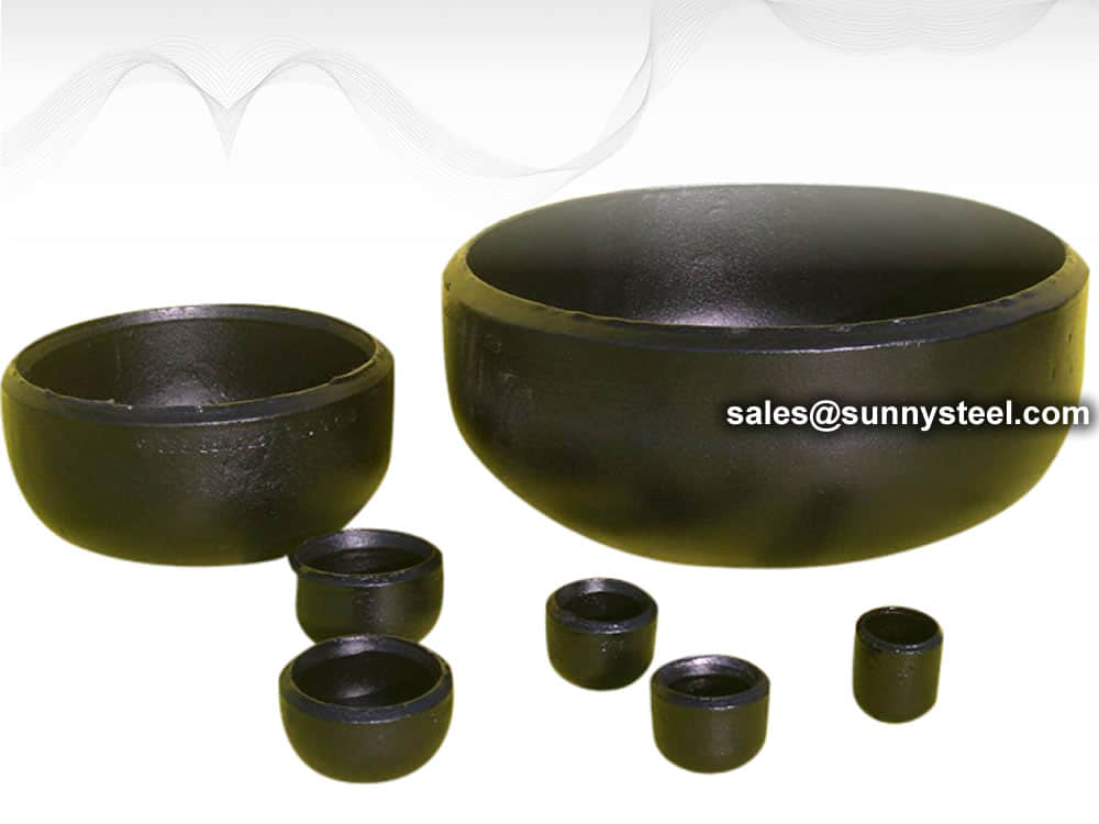
Carbon steel butt welded pipe caps are made of carbon steel plates connected to steel pipes by welding, and the diameter of the cap is larger than that of the forged steel cap.
Carbon steel pipe cap is also known as head cap which is used to weld or install on the male thread of end of pipes for blocking the pipelines. It has same function as plug and blind flange.
Standard ASME B16.9 takes into consideration many variables which then act as a recommendation for the manufacturer of wrought alloy buttwelding fittings produced in a factory such as elbows, caps, crosses, tees, reducers etc. These fittings including the pipe end caps are required to conform to the values such as ratings, testing methods used, overall dimensions, tolerances that are given, as well as markings that need to be on the fitting. Although the pipe ends could be produced with their size ranging anywhere from DN 15 to DN 1200, the size chosen will eventually depend on the requirement of the industry.

Pipe caps fit over or are welded onto the end of a pipe, providing a liquid or gas tight seal.
End Caps are used for connecting pipes of different diameters and find wide applications in various chemicals, construction industries, paper, cement & ship builders.
Pipe caps are widely well-known for the utmost output and outstanding results that it gives.
It is commonly made from the one steel plate, so it should be seamless. The pipe end caps are available in various shapes, like the hemispherical, oval, round etc.
Before purchasing pipe caps in bulk, the buyer should take into account a number of crucial criteria. The following crucial requirements must be taken into account:
This characteristic is appropriate for caps with a round form when the item that has to be protected has a male NPT thread.
This size choice is only appropriate for caps with a round form and a male BSP thread on the item to be capped.
Only round caps and plugs may be made with this crucial size. The primary thread diameter is the most crucial factor to take into account when fittings have straight threads. However, when a cap, plug, or item to be capped has a tapered (NPT or BSP) thread, its size is not a crucial factor to take into account.
The size and shape of pipe caps are other crucial factors to take into account. distinct pipe caps have distinct features. Features include:
Round Caps: The flange, slotted head, knurled or faceted head, retaining head, and tear tab are all common characteristics of round caps. A flange is designed to make it simple to remove pipes or tubes or to provide additional protection. Additionally, flanges aid in preventing inadvertent plug ejection through the aperture. A screwdriver makes it simple to put on or take off slotted caps. Typically, only threaded caps and plugs are intended to be used with knurled or faceted heads. Installation and removal are hassle-free using facets or knurls. It is simple to remove pipe caps that have a tear-tab or strip supplied.
Square or Rectangular Cap: When choosing a square or rectangular cap, the length and breadth should be taken into account the most. For square caps, the length and breadth are the same dimension, but the width is the smaller cross sectional measurement for rectangular caps.
ASTM A234/A234M is a standard specification for piping fittings of wrought carbon steel and alloy steel for moderate and high-temperature service. This specification covers several grades of fittings that are used in various applications in the oil and gas, petrochemical, and power generation industries.
Download PDF| Grade | Type | C | Si | S | P | Mn | Cr | Ni | Mo | Other | ób | ós | δ5 |
|---|---|---|---|---|---|---|---|---|---|---|---|---|---|
| WPB | 0.3 | 0.1min | 0.058 | 0.05 | 0.29-1.06 | 0.4 | 0.4 | 0.15 | V:0.06;Nb:0.02 | 415-585 | 240 | 22 | 197 |
| WPC | 0.35 | 0.1min | 0.058 | 0.05 | 0.29-1.06 | 0.4 | 0.4 | 0.15 | V:0.06;Nb:0.02 | 485-655 | 275 | 22 | 197 |
| WP1 | 0.28 | 0.1-0.5 | 0.045 | 0.045 | 0.3-0.9 | 0.44-0.65 | 380-550 | 205 | 22 | 197 | |||
| WP12 CL1 | 0.05-0.2 | 0.6 | 0.045 | 0.045 | 0.3-0.8 | 0.8-1.25 | 0.44-0.65 | 415-585 | 220 | 22 | 197 | ||
| WP12 CL2 | 0.05-0.2 | 0.6 | 0.045 | 0.045 | 0.3-0.8 | 0.8-1.25 | 0.44-0.65 | 485-655 | 275 | 22 | 197 | ||
| WP11 CL1 | 0.05-0.15 | 0.5-1 | 0.03 | 0.03 | 0.3-0.6 | 1-1.5 | 0.44-0.65 | 415-585 | 205 | 22 | 197 | ||
| WP11 CL2 | 0.05-0.2 | 0.5-1 | 0.04 | 0.04 | 0.3-0.8 | 1-1.5 | 0.44-0.65 | 485-655 | 275 | 22 | 197 | ||
| WP11 CL3 | 0.05-0.2 | 0.5-1 | 0.04 | 0.04 | 0.3-0.8 | 1-1.5 | 0.44-0.65 | 520-690 | 310 | 22 | 197 | ||
| WP22 CL1 | 0.05-0.15 | 0.5 | 0.04 | 0.04 | 0.3-0.6 | 1.9-2.6 | 0.87-1.13 | 415-585 | 205 | 22 | 197 | ||
| WP22 CL3 | 0.05-0.15 | 0.5 | 0.04 | 0.04 | 0.3-0.6 | 1.9-2.6 | 0.87-1.13 | 520-690 | 310 | 22 | 197 | ||
| WP5 CL1 | 0.15 | 0.5 | 0.03 | 0.04 | 0.3-0.6 | 4-6 | 0.44-0.65 | 415-585 | 205 | 22 | 217 | ||
| WP5 CL3 | 0.15 | 0.5 | 0.03 | 0.04 | 0.3-0.6 | 4-6 | 0.44-0.65 | 520-690 | 310 | 22 | 217 | ||
| WP9 CL1 | 0.15 | 1 | 0.03 | 0.03 | 0.3-0.6 | 8-10 | 0.9-1.1 | 415-585 | 205 | 22 | 217 | ||
| WP9 CL3 | 0.15 | 1 | 0.03 | 0.03 | 0.3-0.6 | 8-10 | 0.9-1.1 | 520-690 | 310 | 22 | 217 | ||
| WPR | 0.2 | 0.05 | 0.045 | 0.4-1.06 | 1.6-2.24 | 435-605 | 315 | 22/28 | 217 | ||||
| WP91 | 0.08-0.12 | 0.2-0.5 | 0.01 | 0.02 | 0.3-0.6 | 8-9.5 | 0.4 | 0.85-1.05 | See sdandard | 585-760 | 415 | 20 | 248 |
| WP911 | 0.09-0.13 | 0.1-0.5 | 0.01 | 0.02 | 0.3-0.6 | 8.5-10.5 | 0.4 | 0.9-1.1 | See sdandard | 620-840 | 440 | 20 | 248 |
For each reduction of 0.01% below the specified C maximum, an increase of 0.06% Mn above the specified maximum will be permitted, up to a maximum of 1.35%.
The sum of Cu, Ni, Cr, and Mo shall not exceed 1.00%.
The sum of Cr and Mo shall not exceed 0.32%.
The maximum carbon equivalent (C.E.) shall be 0.50, based on heat analysis and the formula C.E.=C+Mn/6+(Cr+Mo+V)/5+(Ni+Cu)/15.
| Tensile Requirements | WPB | WPC, WP11CL2 | WP11CL1 | WP11CL3 |
|---|---|---|---|---|
| Tensile Strength, min, ksi[MPa] (0.2% offset or 0.5% extension-under-load) |
60-85 [415-585] |
70-95 [485-655] |
60-85 [415-585] |
75-100 [520-690] |
| Yield Strength, min, ksi[MPa] | 32 [240] |
40 [275] |
30 [205] |
45 [310] |
ASME B16.9 Standard covers overall dimensions, tolerances,ratings, testing, and markings for factory-made wrought buttwelding fittings in sizes NPS 1⁄2 through NPS 48 (DN 15 through DN 1200).
Download PDF| Nominal | Outside Diameter | 90° Elbows | 45° Elbows | 180° Returns | ||||
|---|---|---|---|---|---|---|---|---|
| Pipe Size |
Long Radius | Short Radius | Long Radius | Long Radius | ||||
| (inches) | (mm) | (inches) | Center to Face | Center to Face | Center to Face | Radius | Center to Center | Back to face |
| (inches) | (inches) | (inches) | (inches) | (inches) | (inches) | |||
| 1/2 | 21.3 | 0.84 | 1.5 | – | 5/8 | 2 | 1.875 | |
| 3/4 | 26.7 | 1.05 | 1.125 | – | 7/16 | 2.25 | 1.6875 | |
| 1 | 33.4 | 1.315 | 1.5 | 1 | 7/8 | 3 | 2.1875 | |
| 1.25 | 42.2 | 1.66 | 1.875 | 1.25 | 1 | 3.75 | 2.75 | |
| 1.5 | 48.3 | 1.9 | 2.25 | 1.5 | 1.125 | 3 | 4.5 | 3.25 |
| 2 | 60.3 | 2.375 | 3 | 2 | 1.375 | 4 | 6 | 4.1875 |
| 2.5 | 73 | 2.875 | 3.75 | 2.5 | 1.75 | 5 | 7.5 | 5.1875 |
| 3 | 88.9 | 3.5 | 4.5 | 3 | 2 | 6 | 9 | 6.25 |
| 3.5 | 101.6 | 4 | 5.25 | 3.5 | 2.25 | 7 | 10.5 | 7.25 |
| 4 | 114.3 | 4.5 | 6 | 4 | 2.5 | 8 | 12 | 8.25 |
| 5 | 141.3 | 5.563 | 7.5 | 5 | 3.125 | 10 | 15 | 10.3125 |
| 6 | 168.3 | 6.625 | 9 | 6 | 3.75 | 12 | 18 | 12.3125 |
| 8 | 219.1 | 8.625 | 12 | 8 | 5 | 12 | 24 | 16.3125 |
| 10 | 273.1 | 10.75 | 15 | 10 | 6.25 | 15 | 30 | 20.375 |
| 12 | 323.9 | 12.75 | 18 | 12 | 7.5 | 18 | 36 | 24.375 |
| NOMINAL PIPE SIZE NPS | ANGULARITY TOLERANCES | ANGULARITY TOLERANCES |
|---|---|---|
| Size | Off Angle Q | Off Plane P |
| ½ to 4 | 0.03 | 0.06 |
| 5 to 8 | 0.06 | 0.12 |
| 10 to 12 | 0.09 | 0.19 |
| 14 to 16 | 0.09 | 0.25 |
| 18 to 24 | 0.12 | 0.38 |
| 26 to 30 | 0.19 | 0.38 |
| 32 to 42 | 0.19 | 0.5 |
| 44 to 48 | 0.18 | 0.75 |
All dimensions are given in inches. Tolerances are equal plus and minus except as noted.
The ASME B16.9 pipe fittings can be used under the jurisdiction of the ASME Boiler & Pressure Vessel Code (BPVC) as well as the ASME Code for pressure piping. Referencing pressure ratings of flanges per ASME B16.5, they can be designated as Classes 150, 300, 600, 900, 1500 and 2500. The allowable pressure ratings for ASME B16.9 pipe fittings may be calculated as for straight seamless pipe of equivalent material in accordance with the rules established in the applicable sections of ASME B31 Code for pressure piping.
The design of butt welding pipe fittings made to ASME B16.9 shall be established by one of the following methods: (a) mathematical analyses contained in pressure vessel or piping codes; (b) proof testing; (c) experimental stress analysis with hydrostatic testing to validate experimental results; (d) detailed stress analysis with results evaluation.
Generally, ASME B16.9 pipe fittings shall be marked to show the following details: “trademark + material grade + wall thickness + size + heat number”. For example, “M ASTM A234 WP5 SCH80 6″ 385“. When steel stamps are used, care shall be taken so that
the marking is not deep enough or sharp enough to cause cracks or to reduce the wall thickness of the fitting below the minimum allowed.
The ASME B16.9 fittings may be made from an extensive range of mateirals covering (1) carbon and low-alloy steels in accordance with ASTM A234 and ASTM A420; (2) austenitic and duplex stainless steels in accordance with ASTM A403 and ASTM A815; (3) nickel alloys in accordance with ASTM B366; (4) aluminum alloys in accordance with ASTM B361; and (5) titanium alloys in accordance with ASTM B363.

Sizes 1/2″ – 48″
End cap is commonly made from the one steel plate, so it should be seamless. The pipe end caps are available in various shapes, like the hemispherical, oval, round etc.
| Out diameter | High size | Wall thickness accord to 'E' | ||
|---|---|---|---|---|
| DN | NPS | E | E1 | E |
| 15 | 1/2 | 25 | 25 | 3.73 |
| 20 | 3/4 | 25 | 25 | 3.91 |
| 25 | 1 | 38 | 38 | 4.55 |
| 32 | 1 1/4 | 38 | 38 | 4.85 |
| 40 | 1 1/2 | 38 | 38 | 5.08 |
| 50 | 2 | 38 | 44 | 5.54 |
| 65 | 2 1/2 | 38 | 51 | 7.01 |
| 80 | 3 | 51 | 64 | 7.62 |
| 90 | 3 1/2 | 64 | 76 | 8.08 |
| 100 | 4 | 64 | 76 | 8.56 |
| 125 | 5 | 76 | 89 | 9.53 |
| 150 | 6 | 89 | 102 | 10.97 |
| 200 | 8 | 102 | 127 | 12.7 |
| 250 | 10 | 127 | 152 | 12.7 |
| 300 | 12 | 152 | 178 | 12.7 |
| 350 | 14 | 165 | 191 | 12.7 |
| 400 | 16 | 178 | 203 | 12.7 |
| 450 | 18 | 203 | 229 | 12.7 |
| 500 | 20 | 229 | 254 | 12.7 |
| 550 | 22 | 254 | 254 | 12.7 |
| 600 | 24 | 267 | 305 | 12.7 |
| 650 | 26 | 267 | ||
| 700 | 28 | 267 | ||
| 750 | 30 | 267 | ||
| 800 | 32 | 267 | ||
| 850 | 34 | 267 | ||
| 900 | 36 | 267 | ||
| 950 | 38 | 305 | ||
| 1000 | 40 | 305 | ||
| 1050 | 42 | 305 | ||
| 1100 | 44 | 343 | ||
| 1150 | 46 | 343 | ||
| 1200 | 48 | 343 | ||
Size range: 1/2 to 56 inches (DN15 to DN1400)
Pressure: SCH5 to SCH160v
Wall Thickness:sch10, sch20, sch30, std, sch40, sch60, xs, sch80, sch100, sch120, sch140, sch160, xxs, sch5s, sch20s, sch40s, sch80s
Max. wall thickness: 200mm
| OD | ND | INCH | SCH20 | SCH40 | SCH80 | STD | XS |
|---|---|---|---|---|---|---|---|
| Weight | Weight | Weight | Weight | Weight | |||
| 88.9 | 80 | 3 | 0.66 | 0.92 | 0.66 | 0.92 | |
| 114.3 | 100 | 4 | 1.17 | 1.67 | 1.17 | 1.67 | |
| 141.3 | 125 | 5 | 1.91 | 2.78 | 1.91 | 2.78 | |
| 168.3 | 150 | 6 | 2.9 | 4.47 | 2.9 | 4.47 | |
| 219.1 | 200 | 8 | 4.09 | 5.19 | 8.05 | 5.19 | 8.05 |
| 273 | 250 | 10 | 6.36 | 9.15 | 12.5 | 9.15 | 12.5 |
| 323.8 | 300 | 12 | 9.08 | 14.4 | 26.8 | 13.2 | 17.3 |
| 355.6 | 350 | 14 | 13.2 | 18.8 | 34.5 | 15.9 | 20.4 |
| 406.4 | 400 | 16 | 16.8 | 26.7 | 47.7 | 20.4 | 26.3 |
| 457.2 | 450 | 18 | 24.8 | 41.8 | 67.7 | 25.9 | 33.6 |
| 508 | 500 | 20 | 32.2 | 54.9 | 91.3 | 32.2 | 42.7 |
| 558.8 | 550 | 22 | 37.7 | 49.9 | |||
| 609.6 | 600 | 24 | 46.3 | 93.1 | 155 | 46.3 | 59.5 |
Based on different materials, pipe caps include carbon steel cap, stainless steel cap, and alloy steel cap etc.
Depending on their construction, pipe caps contain threaded cap, tapered cap and anti-roll cap etc.

| Outside diameter mm |
Wall thickness mm |
Height mm |
Weight kg |
|---|---|---|---|
| D | s1 | ||
| 21,3 | 2,0 | 25,0 | 0,060 |
| 26,9 | 2,3 | 32,0 | 0,070 |
| 33,7 | 2,6 | 38,0 | 0,110 |
| 3,2 | 0,130 | ||
| 42,4 | 2,6 | 38,0 | 0,130 |
| 3,6 | 0,170 | ||
| 48,3 | 2,6 | 38,0 | 0,200 |
| 4,0 | 0,230 | ||
| 60,3 | 2,9 | 38,0 | 0,280 |
| 4,5 | 0,320 | ||
| 76,1 | 2,9 | 38,0 | 0,340 |
| 5,0 | 0,390 | ||
| 88,9 | 3,2 | 51,0 | 0,530 |
| 5,6 | 0,700 | ||
| 108,0 | 3,6 | 64,0 | 1,000 |
| 114,3 | 3,6 | 64,0 | 1,000 |
| 6,3 | 1,500 | ||
| 133,0 | 4,0 | 76,0 | 1,600 |
| 139,7 | 4,0 | 76,0 | 1,700 |
| 6,3 | 2,500 | ||
| 159,0 | 4,5 | 90,0 | 2,400 |
| 168,3 | 4,5 | 89,0 | 2,650 |
| 7,1 | 3,550 | ||
| 219,0 | 6,3 | 100,0 | 5,550 |
| 8,0 | 6,700 | ||
| 273,0 | 6,3 | 127,0 | 8,800 |
| 323,9 | 7,1 | 152,0 | 14,000 |
| 355,6 | 8,0 | 165,0 | 16,500 |
| 406,4 | 8,8 | 178,0 | 18,200 |
| 508,0 | 11,0 | 229,0 | 38,000 |

ISO - dimensions
| dimensions d1 x s | height L | weight / kg |
|---|---|---|
| 21,3 x 2,0 | 9,0 | 0,01 |
| 26,9 x 2,0 | 9,0 | 0,01 |
| 33,7 x 2,0 | 13,0 | 0,02 |
| 42,4 x 2,0 | 13,0 | 0,04 |
| 48,3 x 2,0 | 13,5 | 0,05 |
| 60,3 x 2,0 | 18,5 | 0,07 |
| 76,1 x 2,0 | 20,5 | 0,10 |
| 88,9 x 2,0 | 25,0 | 0,15 |
| 114,3 x 2,0 | 28,0 | 0,26 |
| 114,3 x 3,0 | 29,0 | 0,39 |
| 139,7 x 3,0 | 38,5 | 0,60 |
| 168,3 x 3,0 | 47,5 | 0,90 |
| 219,1 x 3,0 | 63,5 | 1,32 |
| 273,0 x 3,0 | 93,0 | 1,95 |
| 323,9 x 3,0 | 102,0 | 2,70 |
| 355,6 x 3,0 | 109,0 | 3,80 |
| 406,4 x 3,0 | 123,0 | 5,00 |
| 457,2 x 3,0 | 123,0 | 6,10 |
| 508,0 x 3,0 | 133,0 | 7,60 |
| dimensions d1 x s | height L | weight / kg |
|---|---|---|
| 20,0 x 2,0 | 9,0 | 0,02 |
| 25,0 x 2,0 | 9,0 | 0,03 |
| 30,0 x 2,0 | 13,5 | 0,03 |
| 35,0 x 2,0 | 13,5 | 0,04 |
| 44,0 x 2,0 | 15,0 | 0,04 |
| 54,0 x 2,0 | 15,0 | 0,05 |
| 70,0 x 2,0 | 19,5 | 0,07 |
| 84,0 x 2,0 | 24,0 | 0,15 |
| 104,0 x 2,0 | 28,0 | 0,20 |
| 129,0 x 2,0 | 37,0 | 0,36 |
| 154,0 x 2,0 | 43,0 | 0,50 |
| 156,0 x 3,0 | 44,0 | 0,94 |
| 204,0 x 2,0 | 62,0 | 0,80 |
| 206,0 x 3,0 | 63,0 | 1,20 |
| 254,0 x 2,0 | 72,0 | 1,30 |
| 256,0 x 3,0 | 73,0 | 1,95 |
| 306,0 x 3,0 | 83,0 | 2,50 |
| Out diameter | High size | Wall thickness accord to 'E' | ||
|---|---|---|---|---|
| DN | NPS | E | E1 | E |
| 15 | 1/2 | 25 | 25 | 3.73 |
| 20 | 3/4 | 25 | 25 | 3.91 |
| 25 | 1 | 38 | 38 | 4.55 |
| 32 | 1 1/4 | 38 | 38 | 4.85 |
| 40 | 1 1/2 | 38 | 38 | 5.08 |
| 50 | 2 | 38 | 44 | 5.54 |
| 65 | 2 1/2 | 38 | 51 | 7.01 |
| 80 | 3 | 51 | 64 | 7.62 |
| 90 | 3 1/2 | 64 | 76 | 8.08 |
| 100 | 4 | 64 | 76 | 8.56 |
| 125 | 5 | 76 | 89 | 9.53 |
| 150 | 6 | 89 | 102 | 10.97 |
| 200 | 8 | 102 | 127 | 12.7 |
| 250 | 10 | 127 | 152 | 12.7 |
| 300 | 12 | 152 | 178 | 12.7 |
| 350 | 14 | 165 | 191 | 12.7 |
| 400 | 16 | 178 | 203 | 12.7 |
| 450 | 18 | 203 | 229 | 12.7 |
| 500 | 20 | 229 | 254 | 12.7 |
| 550 | 22 | 254 | 254 | 12.7 |
| 600 | 24 | 267 | 305 | 12.7 |
| 650 | 26 | 267 | ||
| 700 | 28 | 267 | ||
| 750 | 30 | 267 | ||
| 800 | 32 | 267 | ||
| 850 | 34 | 267 | ||
| 900 | 36 | 267 | ||
| 950 | 38 | 305 | ||
| 1000 | 40 | 305 | ||
| 1050 | 42 | 305 | ||
| 1100 | 44 | 343 | ||
| 1150 | 46 | 343 | ||
| 1200 | 48 | 343 | ||
| D(inch) | DN | OD | SCH5s | SCH10s | SCH10 | SCH20 | SCH30 | SCH40s | STD | SCH40 |
|---|---|---|---|---|---|---|---|---|---|---|
| 1/8" | 6 | 10.3 | - | 1.24 | 1.73 | 1.73 | 1.73 | |||
| 1/4" | 8 | 13.7 | - | 1.65 | - | - | - | 2.24 | 2.24 | 2.24 |
| 3/8" | 10 | 17.1 | - | 1.65 | - | - | - | 2.31 | 2.31 | 2.31 |
| 1/2" | 15 | 21.3 | 1.65 | 2.11 | - | - | - | 2.77 | 2.77 | 2.77 |
| 3/4" | 20 | 26.7 | 1.65 | 2.11 | - | - | - | 2.87 | 2.87 | 2.87 |
| 1" | 25 | 33.4 | 1.65 | 2.77 | - | - | - | 3.38 | 3.38 | 3.38 |
| 11/4" | 32 | 42.2 | 1.65 | 2.77 | - | - | - | 3.56 | 3.56 | 3.56 |
| 11/2" | 40 | 48.3 | 1.65 | 2.77 | - | - | - | 3.68 | 3.68 | 3.68 |
| 2" | 50 | 60.3 | 1.65 | 2.77 | - | - | - | 3.91 | 3.91 | 3.91 |
| 21/2" | 65 | 73 | 2.11 | 3.05 | - | - | - | 5.16 | 5.16 | 5.16 |
| 3" | 80 | 88.9 | 2.11 | 3.05 | - | - | - | 5.49 | 5.49 | 5.49 |
| 31/2" | 90 | 101.6 | 2.11 | 3.05 | - | - | - | 5.74 | 5.74 | 5.74 |
| 4" | 100 | 114.3 | 2.11 | 3.05 | - | - | - | 6.02 | 6.02 | 6.02 |
| 5" | 125 | 141.3 | 2.77 | 3.4 | - | - | - | 6.55 | 6.55 | 6.55 |
| 6" | 150 | 168.3 | 2.77 | 3.4 | - | - | - | 7.11 | 7.11 | 7.11 |
| 8" | 200 | 219.1 | 2.77 | 3.76 | - | 6.35 | 7.04 | 8.18 | 8.18 | 8.18 |
| 10" | 250 | 273.1 | 3.4 | 4.19 | - | 6.35 | 7.8 | 9.27 | 9.27 | 9.27 |
| 12" | 300 | 323.9 | 3.96 | 4.57 | - | 6.35 | 8.83 | 9.53 | 9.53 | 10.31 |
| 14" | 350 | 355.6 | 3.96 | 4.78 | 6.35 | 7.92 | 9.53 | - | 9.53 | 11.13 |
| 16" | 400 | 406.4 | 4.19 | 4.78 | 6.35 | 7.92 | 9.53 | - | 9.53 | 12.7 |
| 18" | 450 | 457.2 | 4.19 | 4.78 | 6.35 | 7.92 | 11.13 | - | 9.53 | 14.27 |
| 20" | 500 | 508 | 4.78 | 5.54 | 6.35 | 9.53 | 12.7 | - | 9.53 | 15.09 |
| 22" | 550 | 558.8 | 4.78 | 5.54 | 6.35 | 9.53 | 12.7 | - | 9.53 | |
| 24" | 600 | 609.6 | 5.54 | 6.35 | 6.35 | 9.53 | 14.27 | - | 9.53 | 17.48 |
| 26" | 650 | 660.4 | - | - | 7.92 | 12.7 | - | - | 9.53 | - |
| 28" | 700 | 711.2 | - | - | 7.92 | 12.7 | 15.88 | - | 9.53 | - |
| 30" | 750 | 762 | 6.35 | 7.92 | 7.92 | 12.7 | 15.88 | - | 9.53 | - |
| 32" | 800 | 812.8 | - | - | 7.92 | 12.7 | 15.88 | - | 9.53 | 17.48 |
| 34" | 850 | 863.6 | - | - | 7.92 | 12.7 | 15.88 | - | 9.53 | 17.48 |
| 36" | 900 | 914.4 | - | - | 7.92 | 12.7 | 15.88 | - | 9.53 | 19.05 |
| 38" | 950 | 965.2 | - | - | - | - | - | - | 9.53 | - |
| 40" | 1000 | 1016 | - | - | - | - | - | - | 9.53 | - |
| 42" | 1050 | 1066.8 | - | - | - | - | - | - | 9.53 | - |
| 44" | 1100 | 1117.6 | - | - | - | - | - | - | 9.53 | - |
| 46" | 1150 | 1168.4 | - | - | - | - | - | - | 9.53 | - |
| 48" | 1200 | 1219.2 | - | - | - | - | - | - | 9.53 | - |
Pipe fitting dimensions are in either metric or Standard English.
Because pipe fitting covers Pipe Fitting Dimensions several aspects, only the most common pipe fitting sizes can be given here. The most applied version is the 90° long radius and the 45° elbow, while the 90° short radius elbow is applied if there is too little space. The function of a 180° elbow is to change direction of flow through 180°. Both, the LR and the SR types have a center to center dimension double the matching 90° elbows. These fittings will generally be used in furnesses or other heating or cooling units.
Some of the standards that apply to buttwelded fittings are listed below. Many organizations such as ASME, ASTM, ISO, MSS, etc. have very well developed standards and specifications for buttwelded fittings. It is always up to the designer to ensure that they are following the applicable standard and company specification, if available, during the design process.
Some widely used pipe fitting standards are as follows:
This is one of the reputed organizations in the world developing codes and standards.
The schedule number for pipe fitting starts from ASME/ANSI B16. The various classifications of ASME/ANSI B16 standards for different pipe fittings are as follows:
This is one of the largest voluntary standards development organizations in the world. It was originally known as the American Society for Testing and Materials (ASTM).
AWWA About – Established in 1881, the American Water Works Association is the largest nonprofit, scientific and educational association dedicated to managing and treating water, the world’s most important resource.
ANSI is a private, non-profit organization. Its main function is to administer and coordinate the U.S. voluntary standardization and conformity assessment system. It provides a forum for development of American national standards. ANSI assigns “schedule numbers”. These numbers classify wall thicknesses for different pressure uses.
The Manufacturers Standardization Society (MSS) of the Valve and Fittings Industry is a non-profit technical association organized for development and improvement of industry, national and international codes and standards for: Valves, Valve Actuators, Valve Modification, Pipe Fittings, Pipe Hangers, Pipe Supports, Flanges and Associated Seals
Piping codes imply the requirements of design, fabrication, use of materials, tests and inspection of various pipe and piping system. It has a limited jurisdiction defined by the code. On the other hand, piping standards imply application design and construction rules and requirements for pipe fittings like adapters, flanges, sleeves, elbows, union, tees, valves etc. Like a code, it also has a limited scope defined by the standard.
“Standards” on pipe fittings are based on certain factors like as follows:
BSP is the U.K. standard for pipe fittings. This refers to a family of standard screw thread types for interconnecting and sealing pipe ends by mating an external (male) with an internal (female) thread. This has been adopted internationally. It is also known as British Standard Pipe Taper threads (BSPT )or British Standard Pipe Parallel (Straight) threads (BSPP ). While the BSPT achieves pressure tight joints by the threads alone, the BSPP requires a sealing ring.
This is the Japanese industrial standards or the standards used for industrial activities in Japan for pipe, tube and fittings and published through Japanese Standards Associations.
National Pipe Thread is a U.S. standard straight (NPS) threads or for tapered (NPT) threads. This is the most popular US standard for pipe fittings. NPT fittings are based on the internal diameter (ID) of the pipe fitting.
We are manufacturer of Flange bolts & Nuts and supply high quality
The AN standard was originally designed for the U.S. Military. Whenever, a pipe fitting is AN fittings, it means that the fittings are measured on the outside diameter of the fittings, that is, in 1/16 inch increments.
For example, an AN 4 fitting means a fitting with an external diameter of approximately 4/16″ or ¼”. It is to be noted that approximation is important because AN external diameter is not a direct fit with an equivalent NPT thread.
Dash size is the standard used to refer to the inside diameter of a hose. This indicates the size by a two digit number which represents the relative ID in sixteenths of an inch. This is also used interchangeably with AN fittings. For example, a Dash “8” fitting means an AN 8 fitting.
ISO is the industrial pipe, tube and fittings standards and specifications from the International Organization for Standardization. ISO standards are numbered. They have format as follows:
“ISO[/IEC] [IS] nnnnn[:yyyy] Title” where
| Standard | Specification |
|---|---|
| ASTM A234 | Standard Specification for Piping Fittings of Wrought Carbon Steel and Alloy Steel for Moderate and High Temperature Service |
| ASTM A420 | Standard Specification for Piping Fittings of Wrought Carbon Steel and Alloy Steel for Low-Temperature Service |
| ASTM A234 WPB | ASTM A234 WPB refers to a specific grade of carbon steel pipe fittings, which are widely used in pressure piping and pressure vessel fabrication for service at moderate and elevated temperatures. |
| ASME B16.9 | ASME B16.9 Standard covers overall dimensions, tolerances,ratings, testing, and markings for factory-made wrought buttwelding fittings in sizes NPS 1⁄2 through NPS 48 (DN 15 through DN 1200). |
| ASME B16.28 | ASME B16.28 Standard covers ratings, overall dimensions, testing, tolerances, and markings for wrought carbon and alloy steel buttwelding short radius elbows and returns. |
| MSS SP-97 | MSS SP-97 Standard Practice covers essential dimensions, finish, tolerances, testing, marking, material, and minimum strength requirements for 90 degree integrally reinforced forged branch outlet fittings of buttwelding, socket welding, and threaded types. |
| ASTM A403 | Standard Specification for Wrought Austenitic Stainless Steel Piping Fittings. |
| DIN | EN | ASME |
|---|---|---|
| St 35.8 I St 35.8 III 15 Mo 3 13 CrMo 4 4 10 CrMo 9 10 St 35 N St 52.0 St 52.4 |
P235GH-TC1 P235GH-TC2 16Mo3 13CrMo4-5 10CrMo9-10 X10CrMoVNb9-1 P215NL P265NL L360NB L360NE P355N P355NL1 P355NH |
WPB WPL6 WPL3 WPHY 52 WP11 WP22 WP5 WP9 WP91 WP92 |
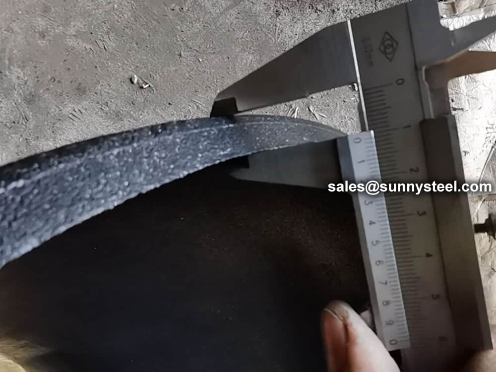
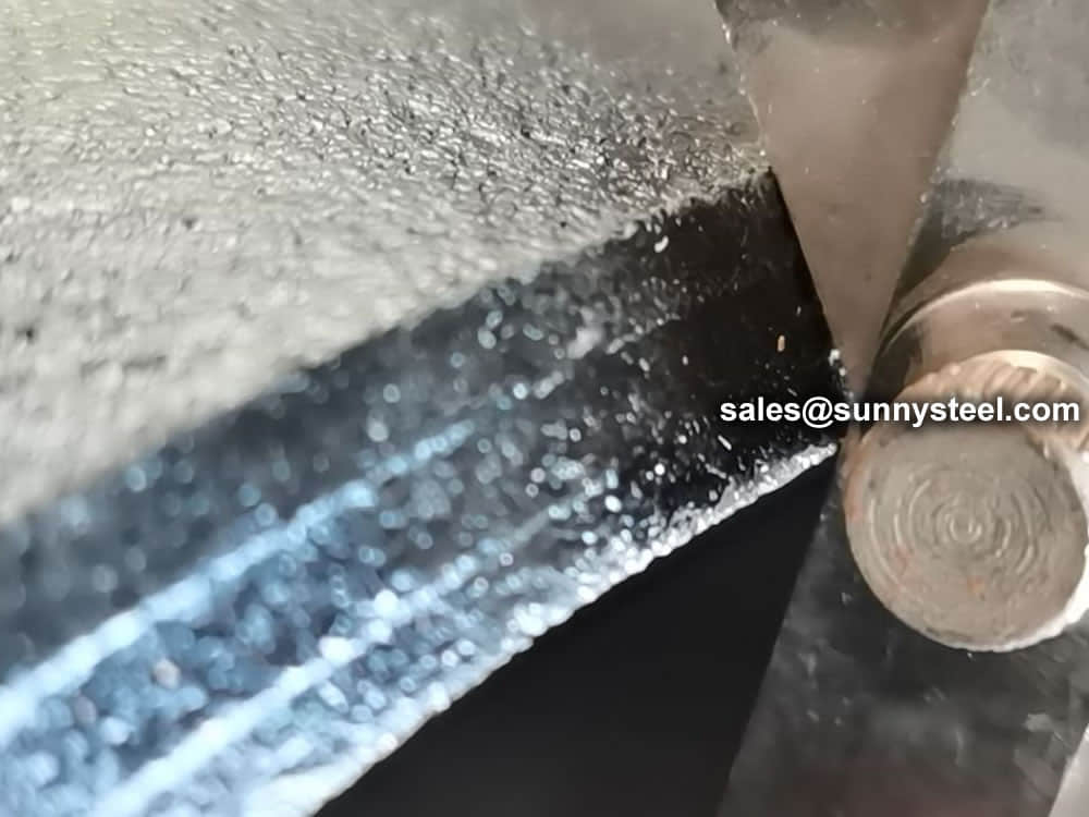
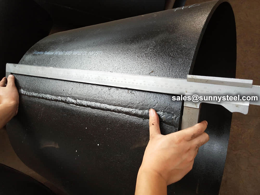
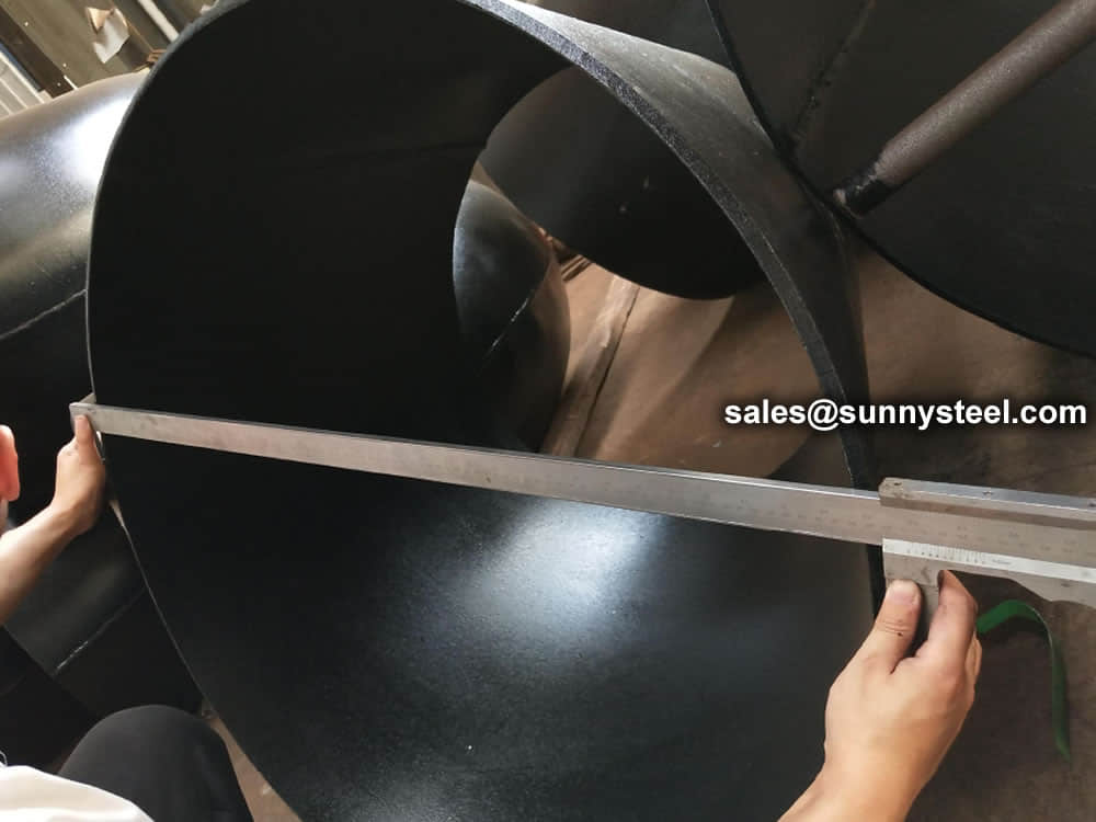
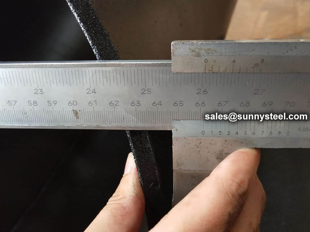
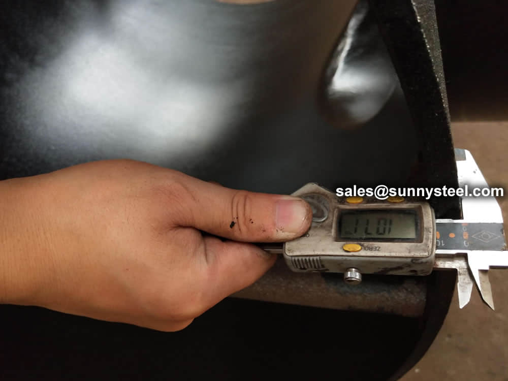
Visual Inspection is conducted on fittings to check any surface imperfections. Both fittings body and weld are checked for any visible surface imperfections such as dents, die marks, porosity, undercuts, etc. Acceptance as per applicable standard.
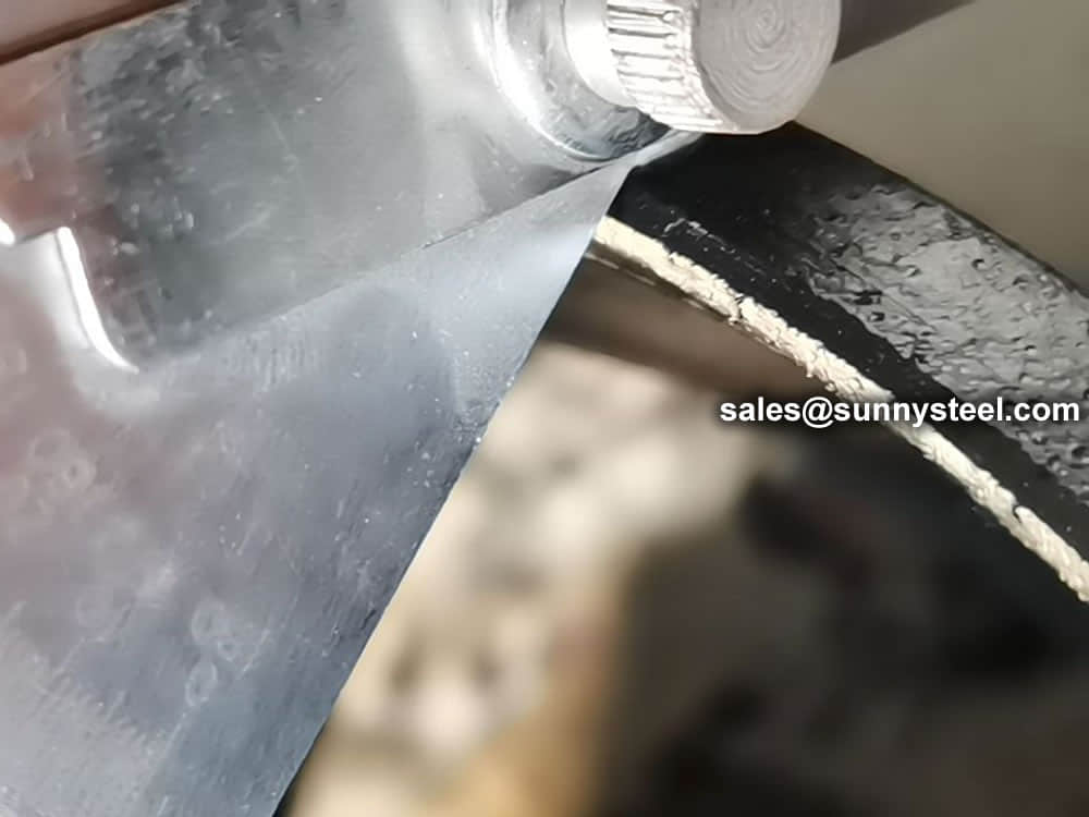
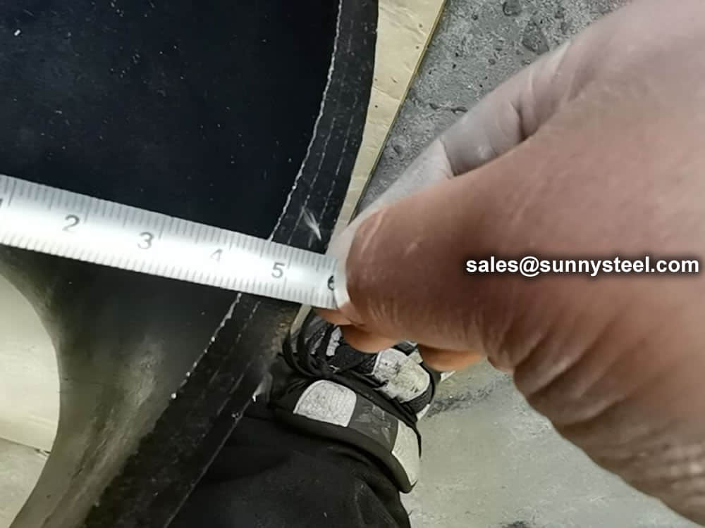
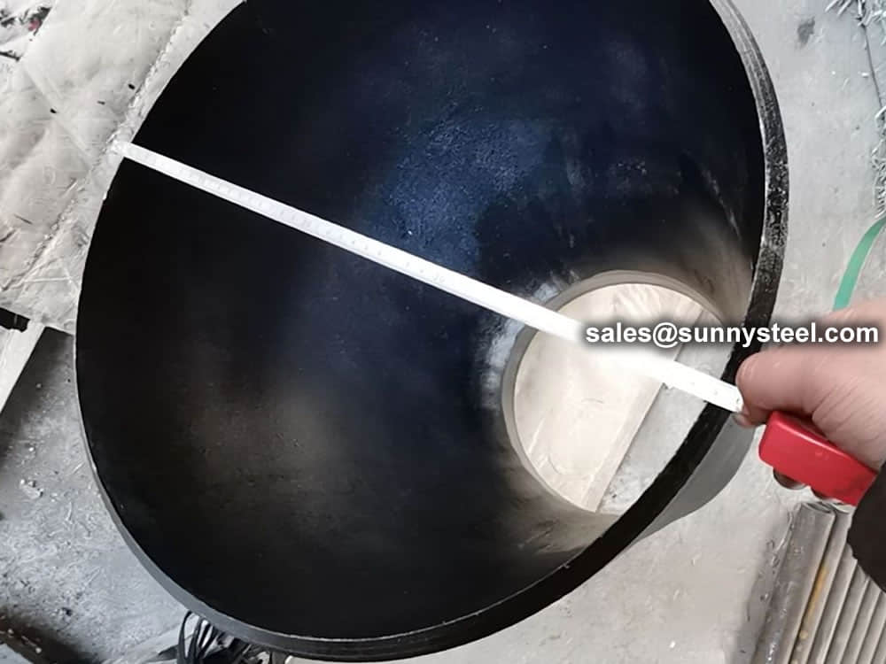
For packing of carbon steel flanges with painting,we would use the bubble wrap to protect the painting.For flanges without painting or oiled with long-term shipment,we would suggest client to use the anti-tarnish paper and plastic bag to prevent the rust.

When you partner with Sunny Steel, you can stop worrying about meeting deadlines thanks to our responsive and timely service. You'll also say goodbye to unnecessary shopping around. Instead, you'll get white glove service from an expert who understands your needs and can get you the materials you need quickly.
