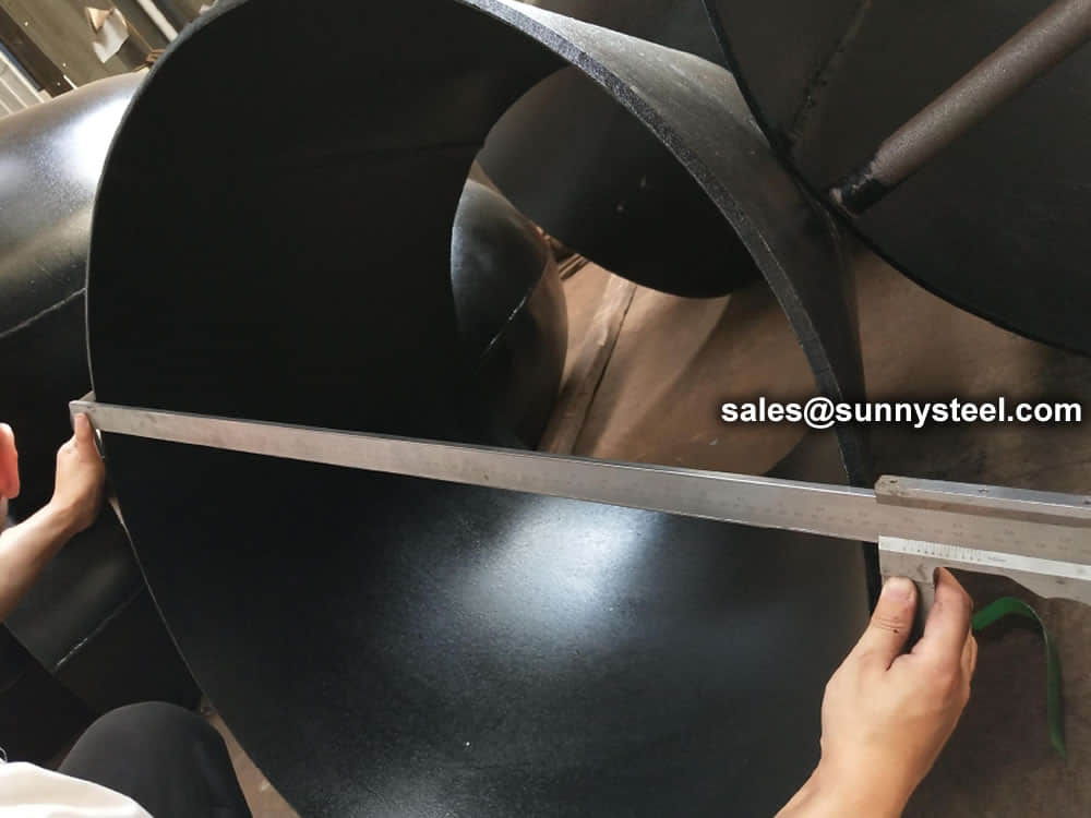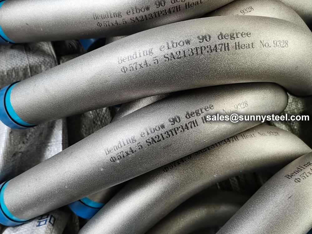
5D Bend Pipe
The radius of a 5D pipe bend is actually what is 5 times the nominal diameter.
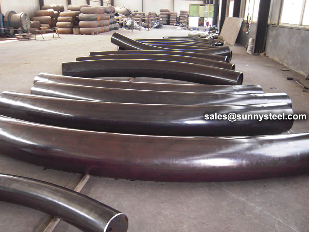
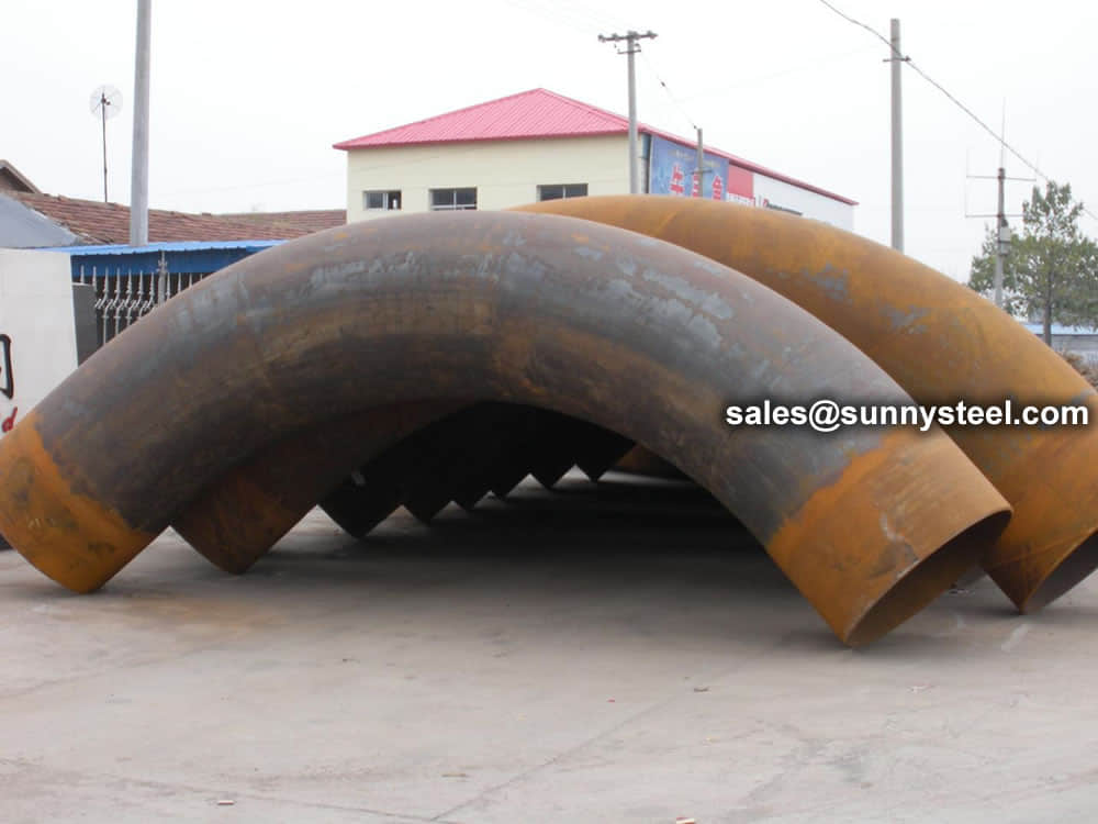
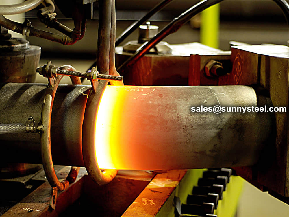
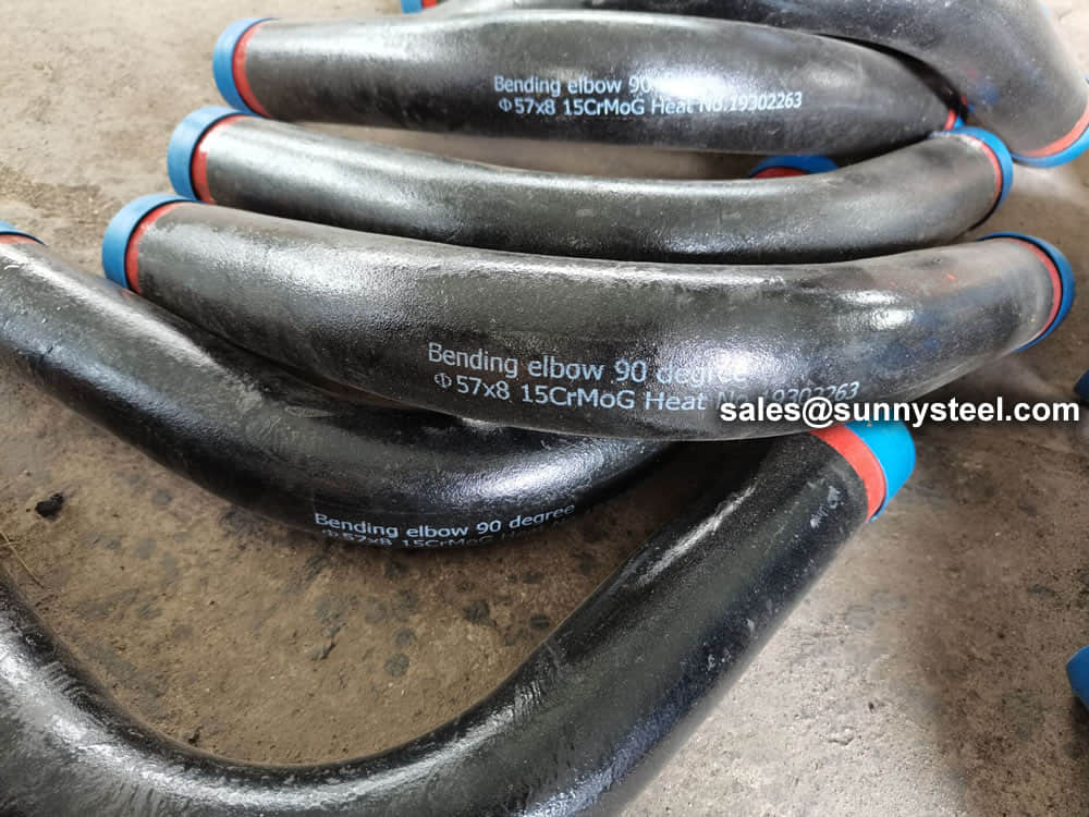
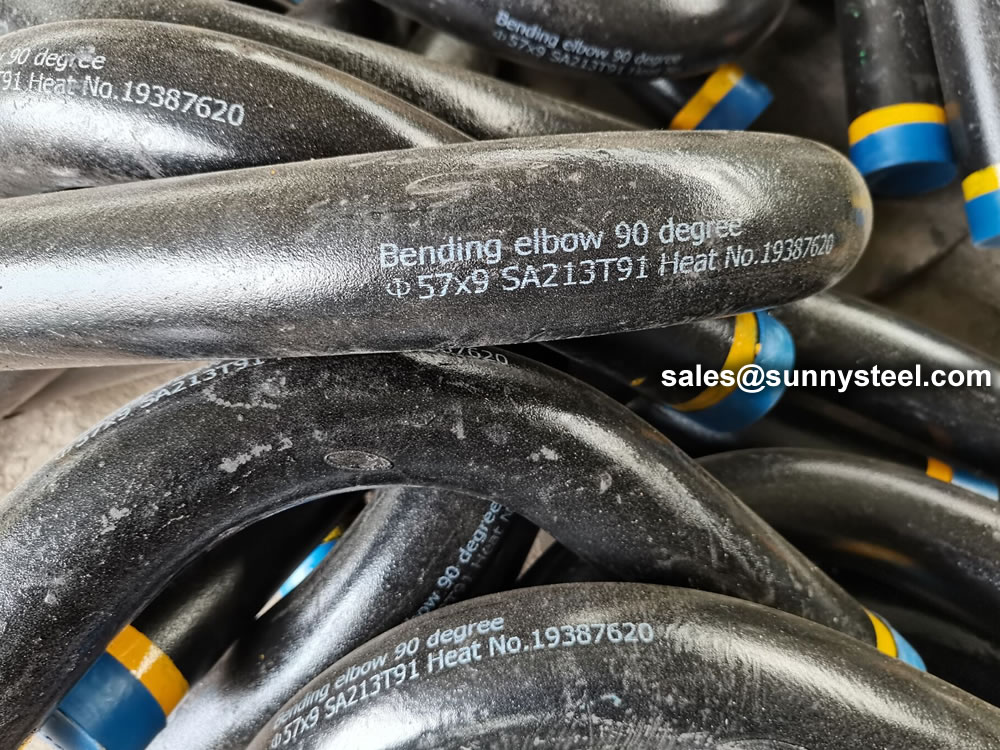
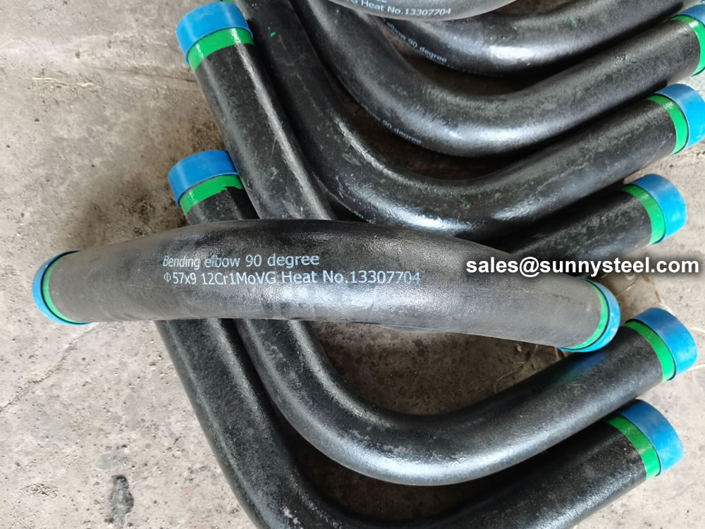
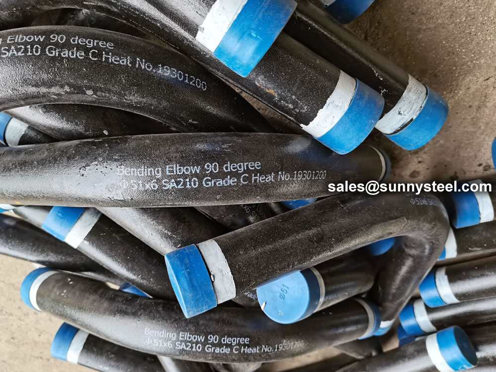
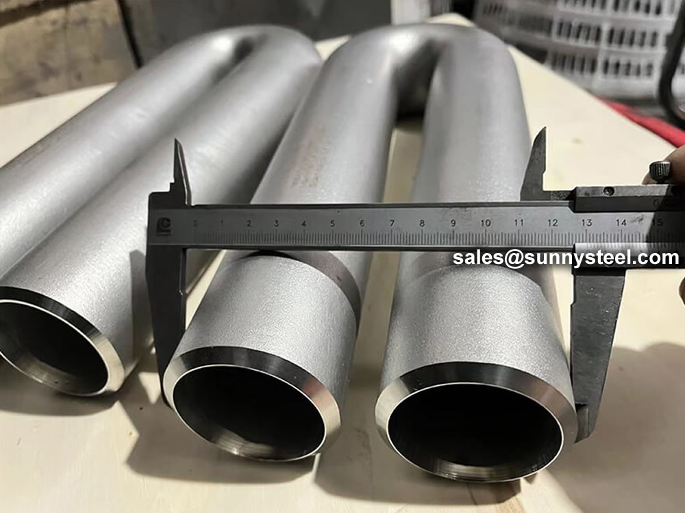
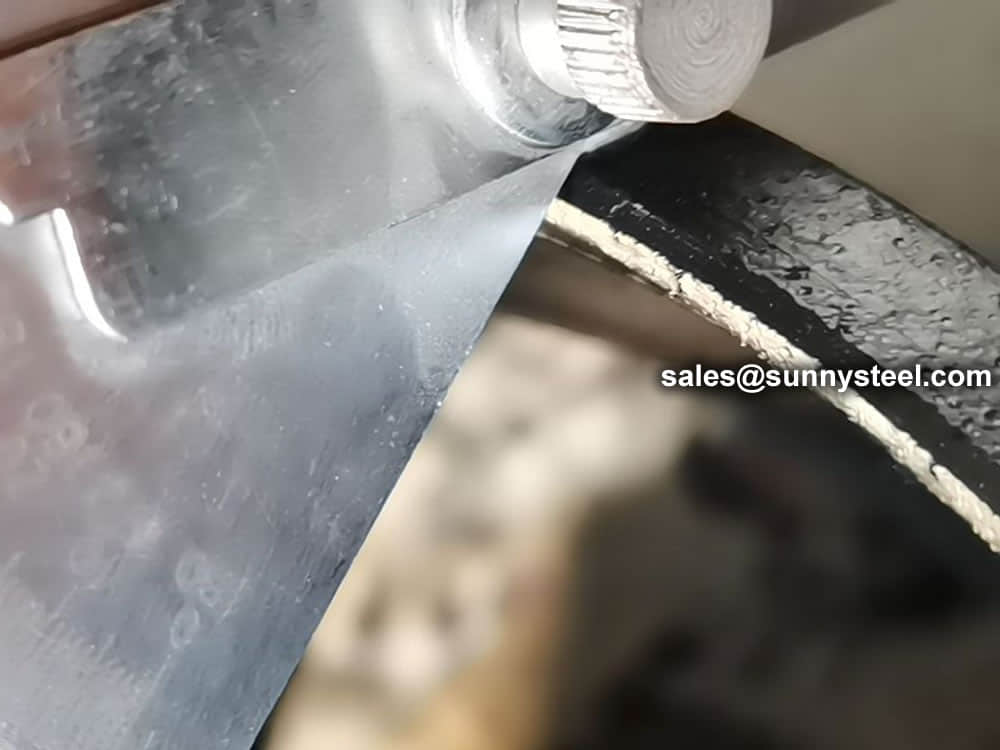
The seamless pipe bend is made by heating and bending the seamless steel pipe.
Our induction pipe bending services are ideal for the the general and process pipework industries, offshore oil and gas production sectors and the power generation. We provide an exceptional range of post-bend heat treatment solutions.
With us we offer, this pipe bends in various types as well including the following:
The 1.5d pipe bend, with a curvature equivalent to 1.5 times the pipe diameter, is ideal for applications requiring sharper turns while maintaining flow efficiency.
Offering a curvature three times the pipe diameter, the 3d pipe bend is commonly used in situations requiring moderate directional changes.
The 4d pipe bend, with a curvature four times the pipe diameter, is suitable for applications that demand a smoother flow trajectory.
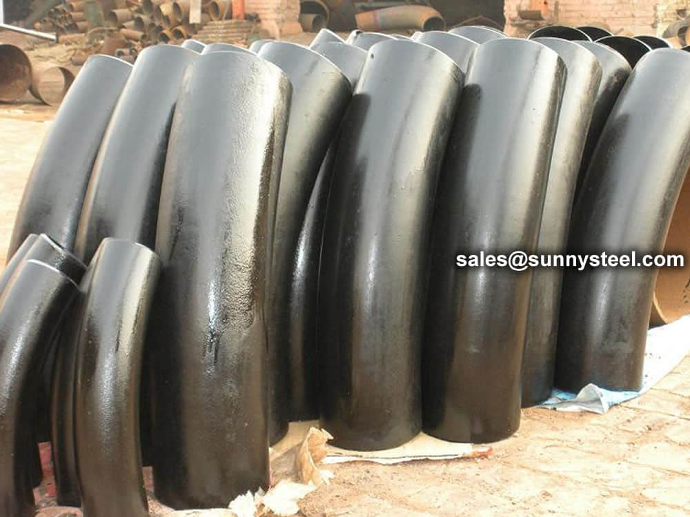
With a curvature five times the pipe diameter, the 5d pipe bend ensures minimal pressure drop and reduced turbulence during fluid conveyance.
The 10d pipe bend, with a curvature ten times the pipe diameter, allows for significant flow redirection without compromising efficiency.
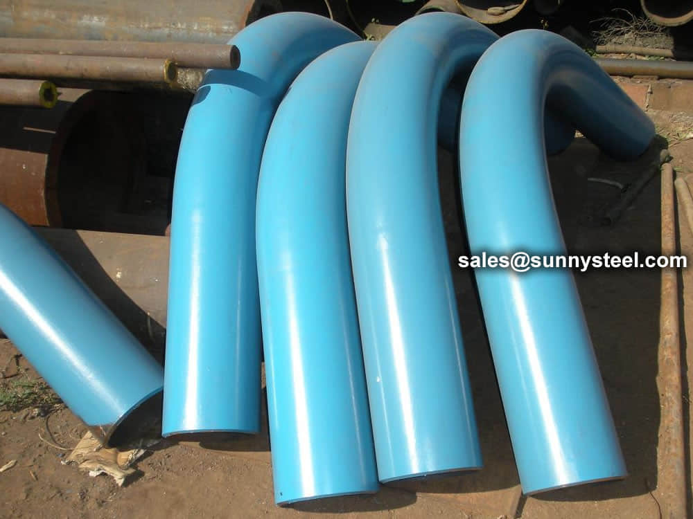
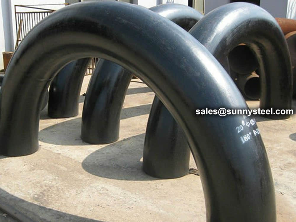
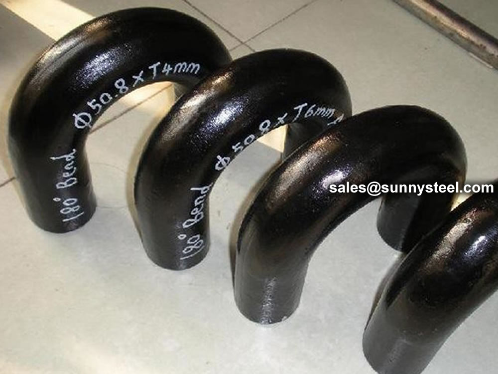
The 180 degrees pipe bend creates a complete U-turn, ideal for applications requiring a complete reversal of flow direction.
| Materials | Grades |
|---|---|
| Stainless Steel | ASTM A403 WP Gr. 304, 304L, 304H, 309, 310, 316, 316L, 316Ti, 317L, 321, 347, 347H, 904L |
| Carbon Steel | ASTM A 234 WPB, WPBW, WPHY 42, WPHY 46, WPHY 52, WPH 60, WPHY 65 & WPHY 70. |
| Low-Temperature Carbon Steel | ASTM A420 WPL3, A420 WPL6 |
| Alloy Steel | ASTM / ASME A/SA 234 Gr. WP 1, WP 5, WP 9, WP 11, WP 12, WP 22, WP 91 |
| Duplex and Super Steel | ASTM A815, ASME SA 815 UNS 31803, UNS 32205 (Dual Certified). |

A pipe bend is the generic term for what is called in piping as an “offset” – a change in direction of the piping. A bend is usually meant to mean nothing more than that there is a “bend”– a change in direction of the piping (usually for some specific reason) – but it lacks specific, engineering definition as to direction and degree. Bends are usually custom-made (using a bending machine) on site and suited for a specific need.
Pipe bends typically have a minimum bending radius of 1.5 times pipe radius (R). If this bending radius is less than 1.5R, it is called Elbow. Reference to any international / industry standard need to be traced. 1.5, 3 and 4.5 R are the most common bending radii in industry.
A pipe bend typically flows smoother since there are not irregular surfaces on the inside of the pipe, nor does the fluid have to change direction abruptly.
The most basic difference of them is the elbow relatively short than bend, R = 1D to 2 D is elbow More than 2D is bend. In the production process, cold bends can use Bending Machine to bend by ready-made straight bend. One-time completed also don’t need second corrosion. But elbow need manufacturers make to order, to do anti-corrosion, order cycle is long. Elbow price is higher than bend. But cost performance is much higher than bend. It is well-known that bend do not have anticorrosive processing is easy damaged, but the price is cheap so are used very much in some demand which not very high engineering.
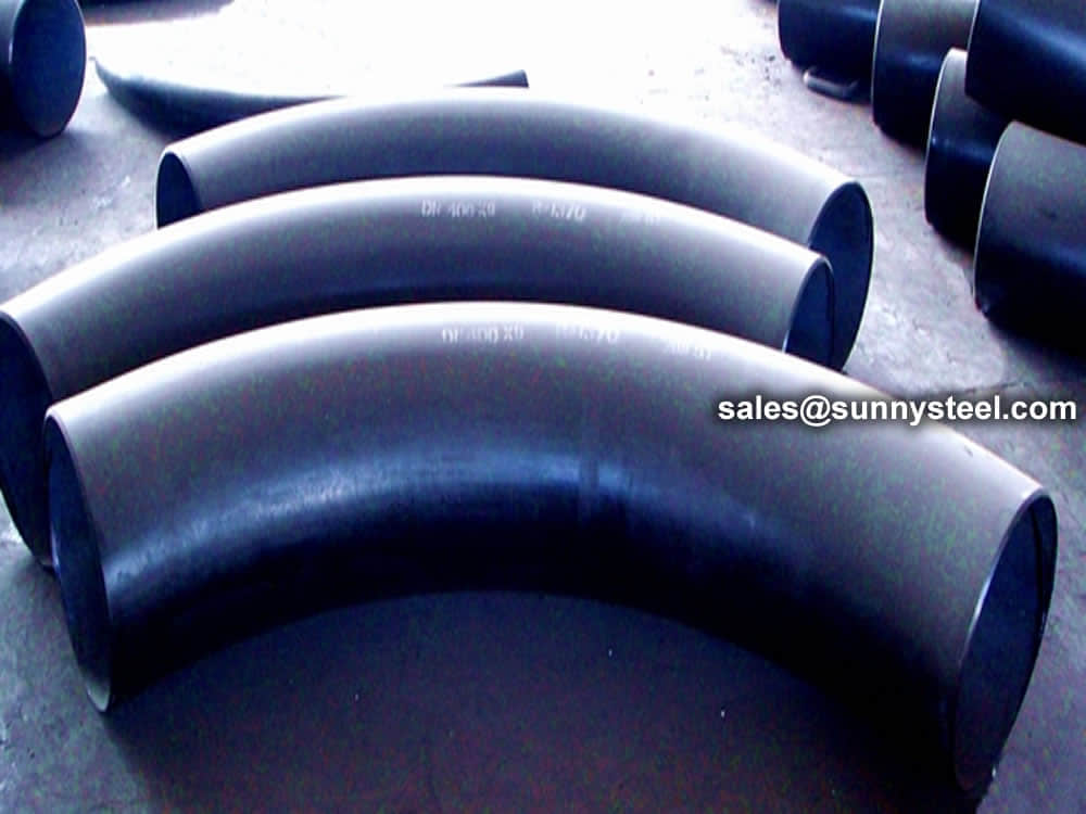
Pipe bends are used in many industries, including chemical, oil and gas, electric, metallurgy and shipbuilding. Pipe bends function as structural passageways to facilitate the transfer of substances, such as water and fuel. Some have a short radius while others have a long radius. Long radius bends give less frictional resistance and allow for less pressure drop when compared to short radius bends. When selecting the type of pipe bend, it’s important to choose one that is compatible to the application.
Bend pipes come in all types of radii, including 3D bends, 4D bends, 5D bends, 8D bends and 10D bends. The radius in 5D bends is five times the nominal diameter. With a 10-inch diameter pipe, the radius of the centerline of the bend would be 50 inches. Pipe bending for the specified radii is both art and science. And with today’s modern machines and advanced software, pipe bending is highly precise. With the right machine, lubrication, tooling and material, achieving the perfect bend is a sure thing.
Although the words bends and elbows are often used as synonyms, there are some differences. Bend is a term for any offset of direction in the piping while elbow is an engineering term. Elbows have limitations to angle, bend radius and size. Most angles are either 45 degrees or 90 degrees. All other offsets are specifically pipe bends. And while elbows have sharp corners, bends never do. The most basic different between a bend and an elbow is the radius of curvature. Bends have a radius more than twice the diameter, and elbows have a radius of curvature between one and two times the size of the pipe’s diameter. All elbows are bends, but not all bends are elbows.
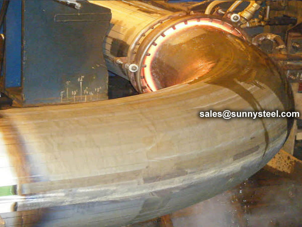
Induction bending is one of the means of bending pipes for 5D and other bends. Local heating, using high-frequency induced electrical power, is applied. An induction coil is placed around the pipe and heats a circumferential area of the pipe at a temperature between 850 to 1100 degrees Celsius. When the right temperature is reached, the pipe moves through an induction coil while an arm applies the bending force. There are many benefits to induction bending. It allows for large radii for smooth flow of fluid, reduces the number of welds in a system and fabricates bends quickly. With faster production, efficiency is ramped up. It’s also a clean process, as no lubrication is needed, and water is recycled.
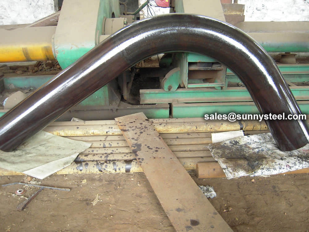
Ram-type bending is an old and effective bending method for bending pipes, including 4D bends and 5D bends. This method is often used in muffler shops. It’s also one of the least expensive ways to bend pipe. A hydraulically driven ram forces the pipe against pivot blocks or rollers. Often, a ram tool is used to produce a concave surface and to prevent stretching on the exterior of the bend. The only downside is that ram-type bending is not as controllable as other methods.
Roll bending is commonly used for pipes in the construction industry. Rolls are positioned vertically or horizontally to produce very large radii. The pinch-style roll bender is one of the machine types used for roll bending. A tube feeds between the lower and upper roll to produce the wanted bend angle. Some applications may require an additional roll to guide the tube outward when the coil is being formed.
The mandrel bending pipe method is effective when the least amount of deformation is desired. The pipe is supported with a mandrel support to bend the pipe. The pipe is drawn through a counter bending die for further bending. This method of pipe bending is used in the manufacture of heat exchanger tubing, dairy tubing and exhausts like turbocharger and custom made ones. This method produces a non-deformed diameter every time.
Rotary draw bending is often used for bending pipe when a constant diameter and good finish are desired. The pipe is drawn through a stationary counter-bending die onto a fixed radius former die. It’s used for roll cages, stock car chassis and other types of pipes.
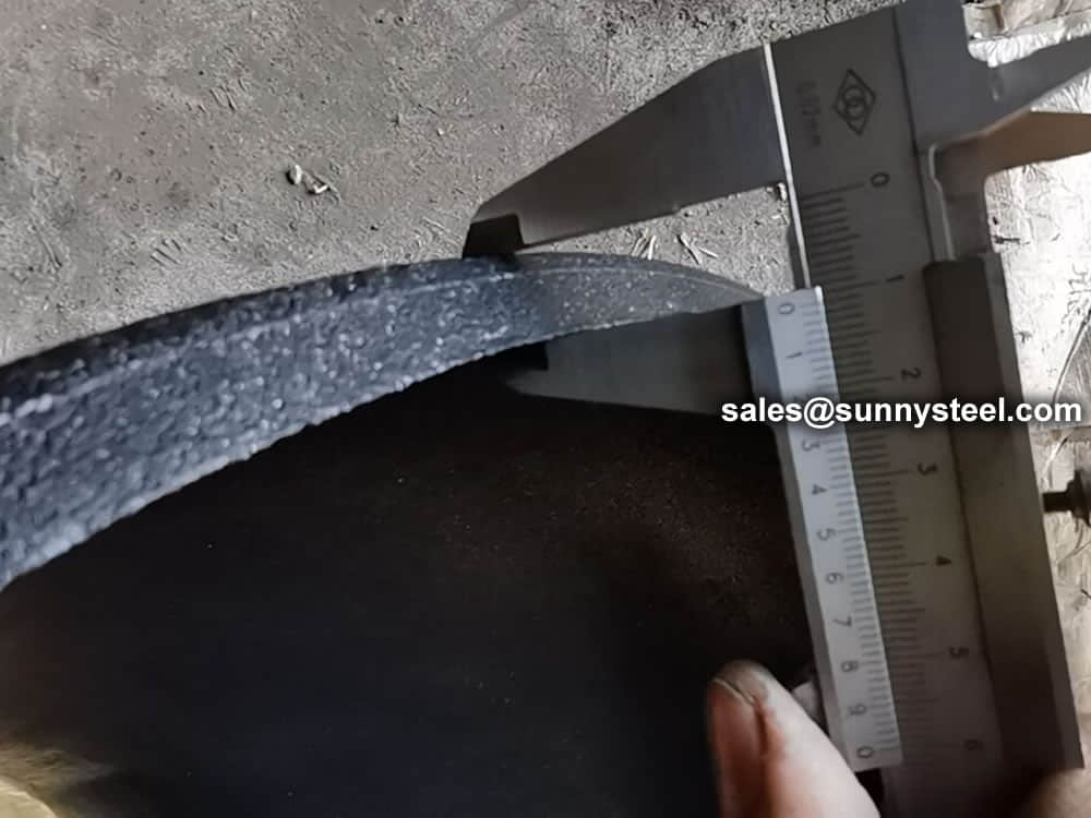
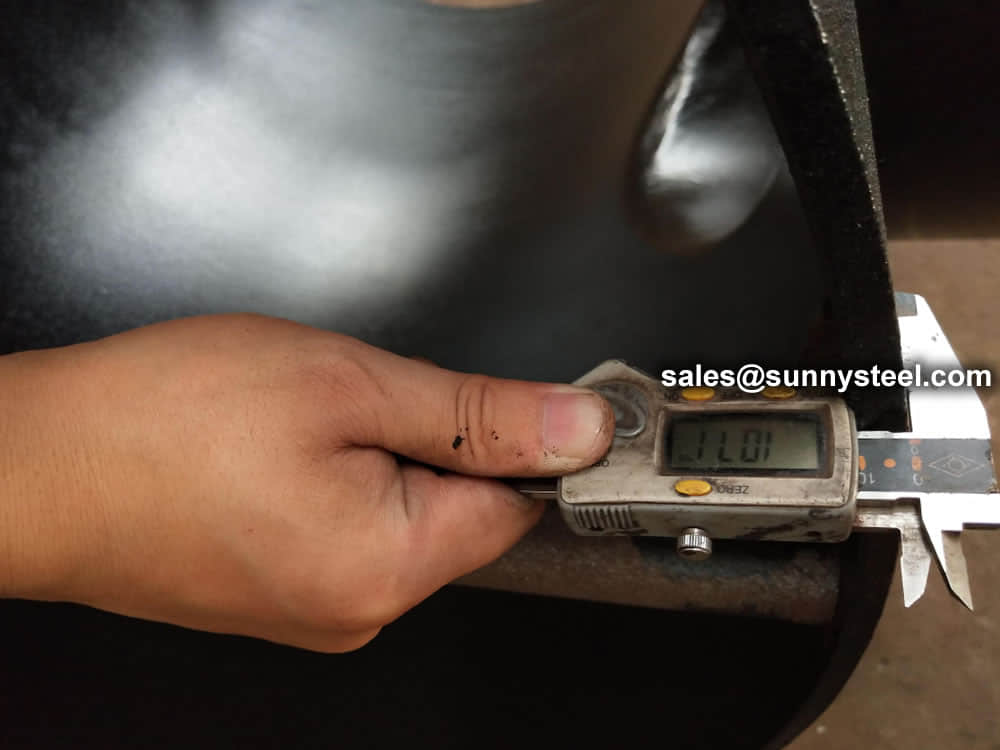
Centerline radius, outside diameter and wall thickness are important variables with bending pipe methods. Plus, every pipe schedule has a nominal wall thickness. And since wall thickness can vary, any variations need to be accounted for. Other bending variables include the neutral line, outside bend radius and inside bend radius. Pipes experience spring back after bending. The harder the pipe and small the bend’s centerline radius, the more spring back, which results in radial growth. Copper pipes have less radial growth than steel pipe due to its less spring back. In pipe bending, consistency, size and quality of the weld seam matter for centerline radius, outside diameter and wall thickness. When these are right, the perfect bend can be created.
 Figure. Flow in a standard, long-radius bend is illustrated here, with typical flow patterns, wear points and reacceleration zone shown
Pipe bends can take a variety of different geometries, which can have a significant influence on particle impact angle. Basic long-radius bends are the most commonly used because they provide the most gradual change in direction for solids, and because the angle of impact on the pipe wall is relatively small, which helps to minimize the risk of attrition or erosion.
Common-radius bends are made by bending standard tubes or pipes (Figure). The radius of curvature, RB, may range from 1 to 24 times the tube diameter, D. Common-radius bends can be loosely classified as follows: Elbow (RB /D = 1 to 2.5); Short radius RB /D = 3 to 7; Long-radius (RB /D = 8 to 14; Long sweep (RB /D = 15 to 24).
As particle impacts occur, particularly against bends, there will be a significant reduction in particle velocity. These particles will then have to be re-accelerated back to their terminal velocity, which will add significantly to the pressure drop — and hence, energy loss — for the conveying system. This is particularly true after short-radius bends.
The pressure drop in a bend depends on the ratio of bend radius to pipe diameter, the gas velocity, Ug, and the internal roughness, k, of the pipe. When a two-phase, gas-solid suspension undergoes a directional change in a pipeline, the bend naturally acts as a segregator of the two phases. Centrifugal forces act on the particles, concentrating them near the outer wall of the bend. Friction coefficients within the bend will be different than those in the adjacent straight sections.
| Dimensions | Standards |
|---|---|
| Outside Diameter | Seamless Pipe Bends(1/2 - 24), ERW/Welded/Fabricated Pipe Bends(2 - 36) |
| Bending Radius | 3D, 5D, 10D or Custom |
| Product Angle | 1.5d Pipe Bends to 180 degree |
| Wall Thickness | 3mm - 40mm/ SCH5, SCH10, SCH20, SCH30, SCH40, STD, XS, SCH60, SCH80, SCH120, SCH140, SCH160, XXS |
| Materials | Stainless Steel, Carbon Steel, Low-Temperature Carbon Steel, Alloy Steel, Duplex, and Super Steel and Nickel Alloys |
Pipe bend offer a smooth transition for fluid or gas flow, reducing the chances of turbulence or obstructions. This results in improved flow efficiency, ensuring that the system operates at its maximum potential while minimizing energy loss.
By carefully curving the piping system, pipe bends minimize pressure drop across the system. This enables the fluid or gas to flow smoothly, reducing the strain on pumps and valves and maintaining consistent pressure levels.
With a wide range of sizes, standards, and types available, pipe bends offer design flexibility. Whether you require a 1.5d pipe bend, 3D Pipe Bend, 4d pipe bend, 5d pipe bend, 10d pipe bend, or a 180-degree pipe bend, we offer the right solution to suit your project specifications.
In congested or limited space environments, pipe bend prove invaluable. Their ability to redirect the flow while taking up less space compared to traditional piping methods allows for more efficient use of available space.
Our pipe bend are manufactured using premium-grade materials, ensuring their durability and resistance to corrosion, abrasion, and extreme temperatures. This longevity reduces maintenance requirements and enhances the lifespan of the entire piping system.
The bend is used to change the direction of run of pipe.it advantage is can matach long distance transition requirements,so it is commonly that bends dimension according to customer design.
Formula:L = R x BL = Length of pipe requiredR = Radius of bendB = Constant from table used to find “L”L =30 x 1.5705 =47.115 in.or 47-1/8”
Standards accord to:
Pressure: SCH5 to SCH160
Bending radius(R): R=3D, 5D, 7D and 12D
Bending angle (θ):15°, 30°, 45°, 60°, 90°, 135°, 180°
Outer diamete(D): D≤1800mm
Wall thickness(T): T≤120mm
Straight Length (L): The length between two ends general from 300mm-1500mm
Example: Find the length of pipe required to make a 90 bend with a radius of 30"
| Nominal pipe | Outside Diameter at Bevel | Center to End | ||||
|---|---|---|---|---|---|---|
| DN size | D1 | D2 | C | M | ||
| Series A | Series B | Series A | Series B | |||
| 20×15 | 26.9 | 25 | 21.3 | 18 | 29 | 29 |
| 25×20 | 33.7 | 32 | 26.9 | 25 | 38 | 38 |
| 25×15 | 33.7 | 32 | 21.3 | 18 | 38 | 38 |
| 32×25 | 42.4 | 38 | 33.7 | 32 | 48 | 48 |
| 32×20 | 42.4 | 38 | 26.9 | 25 | 48 | 48 |
| 32×15 | 42.4 | 38 | 21.3 | 18 | 48 | 48 |
| 40×32 | 48.3 | 45 | 42.4 | 38 | 57 | 57 |
| 40×25 | 48.3 | 45 | 33.7 | 32 | 57 | 57 |
| 40×20 | 48.3 | 45 | 26.7 | 25 | 57 | 57 |
| 40×15 | 48.3 | 45 | 21.3 | 18 | 57 | 57 |
| 50×40 | 60.3 | 57 | 48.3 | 45 | 64 | 60 |
| 50×32 | 60.3 | 57 | 42.4 | 38 | 64 | 57 |
| 50×25 | 60.3 | 57 | 33.7 | 32 | 64 | 51 |
| 50×20 | 60.3 | 57 | 26.9 | 25 | 64 | 44 |
| 65×50 | 76.1(73) | 76 | 60.3 | 57 | 76 | 70 |
| 65×40 | 76.1(73) | 76 | 48.3 | 45 | 76 | 67 |
| 65×32 | 76.1(73) | 76 | 42.4 | 38 | 76 | 64 |
| 65×25 | 76.1(73) | 76 | 33.7 | 32 | 76 | 57 |
| 80×65 | 88.9 | 89 | 76.1(73) | 76 | 86 | 83 |
| 80×50 | 88.9 | 89 | 60.3 | 57 | 86 | 76 |
| 80×40 | 88.9 | 89 | 48.3 | 45 | 86 | 73 |
| 80×32 | 88.9 | 89 | 42.4 | 38 | 86 | 70 |
| 90×80 | 101.6 | - | 88.9 | - | 95 | 92 |
| 90×65 | 101.6 | - | 76.1(73) | - | 95 | 89 |
| 90×50 | 101.6 | - | 60.3 | - | 95 | 83 |
| 90×40 | 101.6 | - | 48.3 | - | 95 | 79 |
| 100×90 | 114.3 | - | 101.6 | - | 105 | 102 |
| 100×80 | 114.3 | 108 | 88.9 | 89 | 105 | 98 |
| 100×65 | 114.3 | 108 | 76.1(73) | 76 | 105 | 95 |
| 100×50 | 114.3 | 108 | 60.3 | 57 | 105 | 89 |
| 100×40 | 114.3 | 108 | 48.3 | 45 | 105 | 86 |
| 125×100 | 139.7 | 133 | 114.3 | 108 | 124 | 117 |
| 125×90 | 139.7 | - | 101.6 | - | 124 | 114 |
| 125×80 | 139.7 | 133 | 88.9 | 89 | 124 | 111 |
| 125×65 | 139.7 | 133 | 76.1(73) | 76 | 124 | 108 |
| 125×50 | 133 | 60.3 | 57 | 124 | 105 | |
| 150×125 | 168.3 | 159 | 139.7 | 133 | 143 | 137 |
| 150×100 | 168.3 | 159 | 114.3 | 108 | 143 | 130 |
| 150×90 | 168.3 | - | 101.6 | - | 143 | 127 |
| 150×80 | 168.3 | 159 | 88.9 | 89 | 143 | 124 |
| 150×65 | 168.3 | 159 | 76.1(73) | 76 | 143 | 121 |
| 200×150 | 219.1 | 219 | 168.3 | 159 | 178 | 168 |
| 200×125 | 219.1 | 219 | 139.7 | 133 | 178 | 162 |
| 200×100 | 219.1 | 219 | 114.3 | 108 | 178 | 156 |
| 200×90 | 219.1 | - | 101.6 | - | 178 | 152 |
| 200×200 | 273 | 273 | 219.1 | 219 | 216 | 208 |
| 200×150 | 273 | 273 | 168.3 | 159 | 216 | 194 |
| 200×125 | 273 | 273 | 139.7 | 133 | 216 | 191 |
| 200×100 | 273 | 273 | 114.3 | 108 | 216 | 184 |
| 300×250 | 323.9 | 325 | 273 | 273 | 254 | 241 |
| 300×200 | 323.9 | 325 | 219.1 | 219 | 254 | 229 |
| 300×150 | 323.9 | 325 | 168.3 | 159 | 254 | 219 |
| 300×125 | 323.9 | 325 | 139.7 | 133 | 254 | 216 |
| 350×300 | 355.6 | 377 | 323.9 | 325 | 279 | 270 |
| 350×250 | 355.6 | 377 | 273 | 273 | 279 | 257 |
| 350×200 | 355.6 | 377 | 219.1 | 219 | 279 | 248 |
| 350×150 | 355.6 | 377 | 168.3 | 159 | 279 | 238 |
| 400×350 | 406.4 | 426 | 355.6 | 377 | 305 | 305 |
| 400×300 | 406.4 | 426 | 323.9 | 325 | 305 | 295 |
| 400×250 | 406.4 | 426 | 273 | 273 | 305 | 283 |
| 400×200 | 406.4 | 426 | 219.1 | 219 | 305 | 273 |
| 400×150 | 406.4 | 426 | 168.3 | 159 | 305 | 264 |
| 450×400 | 457.2 | 478 | 406.4 | 426 | 343 | 330 |
| 450×350 | 457.2 | 478 | 355.6 | 377 | 343 | 330 |
| 450×300 | 457.2 | 478 | 323.9 | 325 | 343 | 321 |
| 450×250 | 457.2 | 478 | 273 | 273 | 343 | 308 |
| 450×200 | 457.2 | 478 | 219.1 | 219 | 343 | 298 |
| 500×450 | 508 | 529 | 457.2 | 478 | 381 | 368 |
| 500×100 | 508 | 529 | 406.4 | 426 | 381 | 356 |
| 500×350 | 508 | 529 | 355.6 | 377 | 381 | 356 |
| 500×300 | 508 | 529 | 323.9 | 325 | 381 | 346 |
| 500×250 | 508 | 529 | 273 | 273 | 381 | 333 |
| 500×200 | 508 | 529 | 219.1 | 219 | 381 | 324 |
| 550×500 | 559 | - | 508 | - | 419 | 406 |
| 550×450 | 559 | - | 457 | - | 419 | 394 |
| 550×400 | 559 | - | 406 | - | 419 | 381 |
| 600×550 | 610 | - | 559 | - | 432 | 432 |
| 600×550 | 610 | 630 | 508 | 530 | 432 | 432 |
| 600×450 | 610 | 630 | 457 | 480 | 432 | 419 |
| 650×600 | 660 | - | 610 | - | 495 | 483 |
| 650×550 | 660 | - | 559 | - | 495 | 470 |
| 650×500 | 660 | - | 508 | - | 495 | 457 |
| 700×650 | 711 | - | 660 | - | 521 | 521 |
| 700×600 | 711 | 720 | 610 | 630 | 521 | 508 |
| 700×550 | 711 | - | 559 | - | 521 | 495 |
| 750×700 | 762 | - | 711 | - | 559 | 546 |
| 750×650 | 762 | - | 660 | - | 559 | 546 |
| 750×600 | 762 | - | 610 | - | 559 | 533 |
| 800×750 | 813 | - | 762 | - | 597 | 584 |
| 800×700 | 813 | 820 | 711 | 720 | 597 | 572 |
| 800×650 | 813 | - | 660 | - | 597 | 572 |
| 850×800 | 864 | - | 813 | - | 635 | 622 |
| 850×750 | 864 | - | 762 | - | 635 | 610 |
| 850×700 | 864 | - | 711 | - | 635 | 597 |
| 900×850 | 914 | - | 864 | - | 673 | 660 |
| 900×800 | 914 | 920 | 813 | 820 | 673 | 648 |
| 900×750 | 914 | - | 762 | - | 673 | 635 |
| 950×900 | 965 | - | 914 | - | 711 | 711 |
| 950×850 | 965 | - | 864 | - | 711 | 698 |
| 950×800 | 965 | - | 813 | - | 711 | 686 |
| 1000×950 | 1016 | - | 965 | - | 749 | 749 |
| 1000×900 | 1016 | 1020 | 914 | 920 | 749 | 737 |
| 1000×8500 | 1016 | - | 864 | - | 749 | 724 |
| 1000×1000 | 1067 | - | 1016 | - | 762 | 711 |
| 1050×950 | 1067 | - | 965 | - | 762 | 711 |
| 1050×900 | 1067 | - | 914 | - | 762 | 711 |
| 1100×1050 | 1118 | - | 1067 | - | 813 | 762 |
| 1100×1000 | 1118 | 1120 | 1016 | 1020 | 813 | 749 |
| 1100×950 | 1118 | - | 965 | - | 813 | 737 |
| 1150×1100 | 1168 | - | 1118 | - | 851 | 800 |
| 1150×1050 | 1168 | - | 1067 | - | 851 | 787 |
| 1150×1000 | 1168 | - | 1016 | - | 851 | 775 |
| 1200×1150 | 1220 | - | 1168 | - | 889 | 838 |
| 1200×1100 | 1220 | 1220 | 1118 | 1120 | 889 | 838 |
| 1200×1050 | 1220 | - | 1067 | - | 889 | 813 |
Just before the final delivery, our merchandise are stringently checked by a team of quality analyzers on varied parameters, which guarantee their flawlessness and durability. In addition, clients can avail these goods from us at competitive rates.
Pipe bends play a vital role in flow control systems, allowing the smooth and efficient redirection of fluids and gases. These components are designed to change the direction of piping systems, allowing the fluid or gas to flow around obstacles or corners with minimal turbulence or pressure loss. By minimising friction and pressure drop, pipe bends help maintain optimum flow rates, reduce energy consumption and improve overall system performance.


Pipe fittings are necessary to join together pipes, or to change the direction of an existing pipe. Pipes and pipe fittings are made of a variety of materials, depending on the fluid or gas being transported. Most pipe fittings tend to be either threaded or able to slip over the pipes they connect. Whether you are using steel pipes of PVC pipes, a chemical solvent is required to create a seal between the pipe and the fittings.
Measure the required length of the pipe to be installed, keeping in mind the extra length required where the pipe will be inserted into the fitting. Mark this length on the pipe.
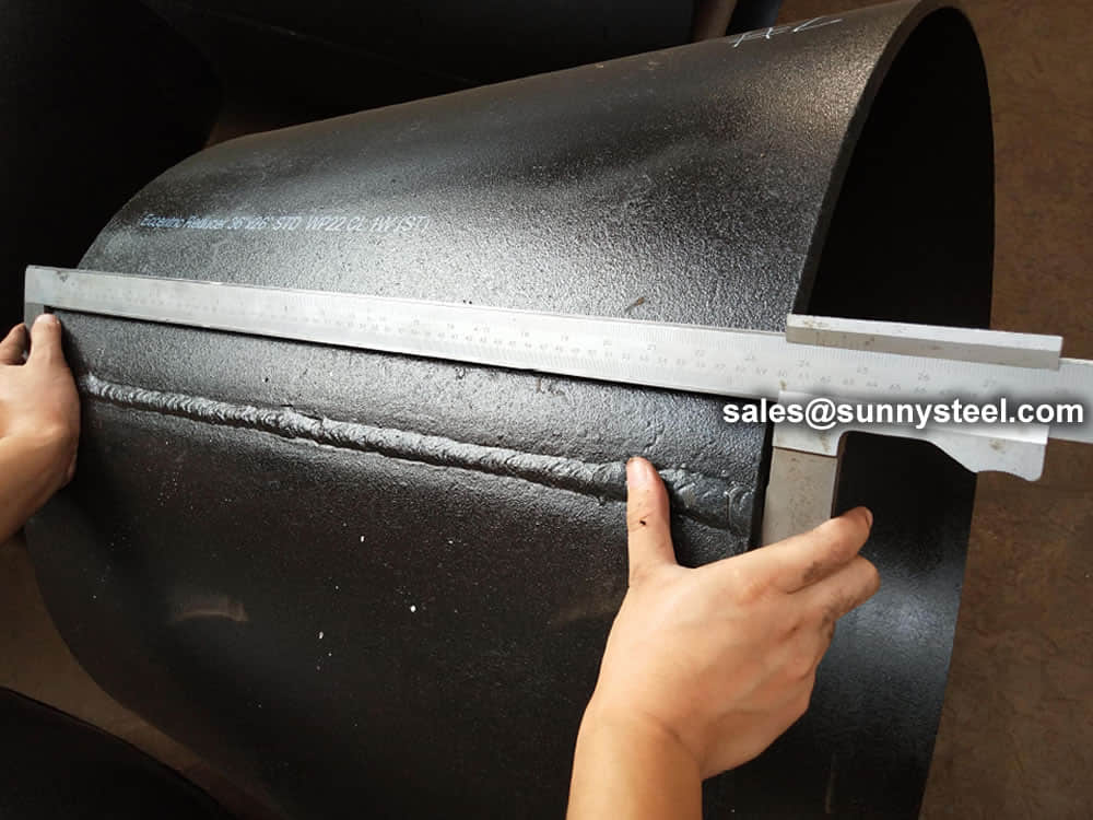
The ends of all buttweld fittings are bevelled, exceeding wall thickness 4 mm for austenitic stainless steel, or 5 mm for ferritic stainless steel. The shape of the bevel depending upon the actual wall thickness. This bevelled ends are needed to be able to make a “Butt weld”.
Welding Bevel acc.to ASME / ANSI B16.9 and ASME / ANSI B16.28
ASME B16.25 covers the preparation of buttwelding ends of piping components to be joined into a piping system by welding. It includes requirements for welding bevels, for external and internal shaping of heavy-wall components, and for preparation of internal ends (including dimensions and dimensional tolerances).
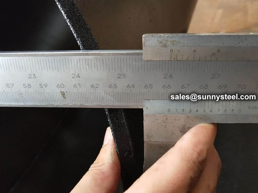
Our in-hourse R&D team developed bevel ends equipment are good using in thickness 2mm to 20mm pipe fittings, guarantee high efficiency and high quality.
These weld edge preparation requirements are also incorporated into the ASME standards (e.g., B16.9, B16.5, B16.34).
ASME B16.25 sets standards for the preparation of the ends of components that need to be welded together.
Cut square or slight chamfer, at manufacturer’s option for :
A pipe fitting is defined as a part used in a piping system, for changing direction, branching or for change of pipe diameter, and which is mechanically joined to the system.
There are many different types of fittings and they are the same in all sizes and schedules as the pipe.
ASME B16.9 Standard covers overall dimensions, tolerances,ratings, testing, and markings for factory-made wrought buttwelding fittings in sizes NPS 1⁄2 through NPS 48 (DN 15 through DN 1200).
Download PDF| Nominal | Outside Diameter | 90° Elbows | 45° Elbows | 180° Returns | ||||
|---|---|---|---|---|---|---|---|---|
| Pipe Size |
Long Radius | Short Radius | Long Radius | Long Radius | ||||
| (inches) | (mm) | (inches) | Center to Face | Center to Face | Center to Face | Radius | Center to Center | Back to face |
| (inches) | (inches) | (inches) | (inches) | (inches) | (inches) | |||
| 1/2 | 21.3 | 0.84 | 1.5 | – | 5/8 | 2 | 1.875 | |
| 3/4 | 26.7 | 1.05 | 1.125 | – | 7/16 | 2.25 | 1.6875 | |
| 1 | 33.4 | 1.315 | 1.5 | 1 | 7/8 | 3 | 2.1875 | |
| 1.25 | 42.2 | 1.66 | 1.875 | 1.25 | 1 | 3.75 | 2.75 | |
| 1.5 | 48.3 | 1.9 | 2.25 | 1.5 | 1.125 | 3 | 4.5 | 3.25 |
| 2 | 60.3 | 2.375 | 3 | 2 | 1.375 | 4 | 6 | 4.1875 |
| 2.5 | 73 | 2.875 | 3.75 | 2.5 | 1.75 | 5 | 7.5 | 5.1875 |
| 3 | 88.9 | 3.5 | 4.5 | 3 | 2 | 6 | 9 | 6.25 |
| 3.5 | 101.6 | 4 | 5.25 | 3.5 | 2.25 | 7 | 10.5 | 7.25 |
| 4 | 114.3 | 4.5 | 6 | 4 | 2.5 | 8 | 12 | 8.25 |
| 5 | 141.3 | 5.563 | 7.5 | 5 | 3.125 | 10 | 15 | 10.3125 |
| 6 | 168.3 | 6.625 | 9 | 6 | 3.75 | 12 | 18 | 12.3125 |
| 8 | 219.1 | 8.625 | 12 | 8 | 5 | 12 | 24 | 16.3125 |
| 10 | 273.1 | 10.75 | 15 | 10 | 6.25 | 15 | 30 | 20.375 |
| 12 | 323.9 | 12.75 | 18 | 12 | 7.5 | 18 | 36 | 24.375 |
| NOMINAL PIPE SIZE NPS | ANGULARITY TOLERANCES | ANGULARITY TOLERANCES |
|---|---|---|
| Size | Off Angle Q | Off Plane P |
| ½ to 4 | 0.03 | 0.06 |
| 5 to 8 | 0.06 | 0.12 |
| 10 to 12 | 0.09 | 0.19 |
| 14 to 16 | 0.09 | 0.25 |
| 18 to 24 | 0.12 | 0.38 |
| 26 to 30 | 0.19 | 0.38 |
| 32 to 42 | 0.19 | 0.5 |
| 44 to 48 | 0.18 | 0.75 |
All dimensions are given in inches. Tolerances are equal plus and minus except as noted.
The ASME B16.9 pipe fittings can be used under the jurisdiction of the ASME Boiler & Pressure Vessel Code (BPVC) as well as the ASME Code for pressure piping. Referencing pressure ratings of flanges per ASME B16.5, they can be designated as Classes 150, 300, 600, 900, 1500 and 2500. The allowable pressure ratings for ASME B16.9 pipe fittings may be calculated as for straight seamless pipe of equivalent material in accordance with the rules established in the applicable sections of ASME B31 Code for pressure piping.
The design of butt welding pipe fittings made to ASME B16.9 shall be established by one of the following methods: (a) mathematical analyses contained in pressure vessel or piping codes; (b) proof testing; (c) experimental stress analysis with hydrostatic testing to validate experimental results; (d) detailed stress analysis with results evaluation.
Generally, ASME B16.9 pipe fittings shall be marked to show the following details: “trademark + material grade + wall thickness + size + heat number”. For example, “M ASTM A234 WP5 SCH80 6″ 385“. When steel stamps are used, care shall be taken so that
the marking is not deep enough or sharp enough to cause cracks or to reduce the wall thickness of the fitting below the minimum allowed.
The ASME B16.9 fittings may be made from an extensive range of mateirals covering (1) carbon and low-alloy steels in accordance with ASTM A234 and ASTM A420; (2) austenitic and duplex stainless steels in accordance with ASTM A403 and ASTM A815; (3) nickel alloys in accordance with ASTM B366; (4) aluminum alloys in accordance with ASTM B361; and (5) titanium alloys in accordance with ASTM B363.

Sizes 1/2″ – 48″
Pipe bends, also known as elbows, are widely used in various industries and applications.

Tube bending is essential for a wide range of industries. Our tube and pipe bending applications are used in everything from the automotive industry to shipbuilding, aerospace and much more. The automotive industry relies on mandrel bending machines to minimise the ovality that occurs on thin-walled tubes when they are bent. Our bending machines also help to eliminate wrinkles on the inside radius of the bend.
Two other industries that rely heavily on high quality tube bending are aerospace and aeronautics. In these industries, bends must be precise and there is no room for error. In aerospace, it is particularly important to produce bends with pinpoint accuracy. Our bending machines are perfect for industrial bending of tubes, pipes, square and rectangular profiles. Our mandrel bending machines can even bend profiles to a centreline radius as small as 1.5 x diameter.
Here are some common applications of pipe bend:


Pipe fitting dimensions are in either metric or Standard English.
Because pipe fitting covers Pipe Fitting Dimensions several aspects, only the most common pipe fitting sizes can be given here. The most applied version is the 90° long radius and the 45° elbow, while the 90° short radius elbow is applied if there is too little space. The function of a 180° elbow is to change direction of flow through 180°. Both, the LR and the SR types have a center to center dimension double the matching 90° elbows. These fittings will generally be used in furnesses or other heating or cooling units.
Some of the standards that apply to buttwelded fittings are listed below. Many organizations such as ASME, ASTM, ISO, MSS, etc. have very well developed standards and specifications for buttwelded fittings. It is always up to the designer to ensure that they are following the applicable standard and company specification, if available, during the design process.
Some widely used pipe fitting standards are as follows:
This is one of the reputed organizations in the world developing codes and standards.
The schedule number for pipe fitting starts from ASME/ANSI B16. The various classifications of ASME/ANSI B16 standards for different pipe fittings are as follows:
This is one of the largest voluntary standards development organizations in the world. It was originally known as the American Society for Testing and Materials (ASTM).
AWWA About – Established in 1881, the American Water Works Association is the largest nonprofit, scientific and educational association dedicated to managing and treating water, the world’s most important resource.
ANSI is a private, non-profit organization. Its main function is to administer and coordinate the U.S. voluntary standardization and conformity assessment system. It provides a forum for development of American national standards. ANSI assigns “schedule numbers”. These numbers classify wall thicknesses for different pressure uses.
The Manufacturers Standardization Society (MSS) of the Valve and Fittings Industry is a non-profit technical association organized for development and improvement of industry, national and international codes and standards for: Valves, Valve Actuators, Valve Modification, Pipe Fittings, Pipe Hangers, Pipe Supports, Flanges and Associated Seals
Piping codes imply the requirements of design, fabrication, use of materials, tests and inspection of various pipe and piping system. It has a limited jurisdiction defined by the code. On the other hand, piping standards imply application design and construction rules and requirements for pipe fittings like adapters, flanges, sleeves, elbows, union, tees, valves etc. Like a code, it also has a limited scope defined by the standard.
“Standards” on pipe fittings are based on certain factors like as follows:
BSP is the U.K. standard for pipe fittings. This refers to a family of standard screw thread types for interconnecting and sealing pipe ends by mating an external (male) with an internal (female) thread. This has been adopted internationally. It is also known as British Standard Pipe Taper threads (BSPT )or British Standard Pipe Parallel (Straight) threads (BSPP ). While the BSPT achieves pressure tight joints by the threads alone, the BSPP requires a sealing ring.
This is the Japanese industrial standards or the standards used for industrial activities in Japan for pipe, tube and fittings and published through Japanese Standards Associations.
National Pipe Thread is a U.S. standard straight (NPS) threads or for tapered (NPT) threads. This is the most popular US standard for pipe fittings. NPT fittings are based on the internal diameter (ID) of the pipe fitting.
We are manufacturer of Flange bolts & Nuts and supply high quality
The AN standard was originally designed for the U.S. Military. Whenever, a pipe fitting is AN fittings, it means that the fittings are measured on the outside diameter of the fittings, that is, in 1/16 inch increments.
For example, an AN 4 fitting means a fitting with an external diameter of approximately 4/16″ or ¼”. It is to be noted that approximation is important because AN external diameter is not a direct fit with an equivalent NPT thread.
Dash size is the standard used to refer to the inside diameter of a hose. This indicates the size by a two digit number which represents the relative ID in sixteenths of an inch. This is also used interchangeably with AN fittings. For example, a Dash “8” fitting means an AN 8 fitting.
ISO is the industrial pipe, tube and fittings standards and specifications from the International Organization for Standardization. ISO standards are numbered. They have format as follows:
“ISO[/IEC] [IS] nnnnn[:yyyy] Title” where
| Standard | Specification |
|---|---|
| ASTM A234 | Standard Specification for Piping Fittings of Wrought Carbon Steel and Alloy Steel for Moderate and High Temperature Service |
| ASTM A420 | Standard Specification for Piping Fittings of Wrought Carbon Steel and Alloy Steel for Low-Temperature Service |
| ASTM A234 WPB | ASTM A234 WPB refers to a specific grade of carbon steel pipe fittings, which are widely used in pressure piping and pressure vessel fabrication for service at moderate and elevated temperatures. |
| ASME B16.9 | ASME B16.9 Standard covers overall dimensions, tolerances,ratings, testing, and markings for factory-made wrought buttwelding fittings in sizes NPS 1⁄2 through NPS 48 (DN 15 through DN 1200). |
| ASME B16.28 | ASME B16.28 Standard covers ratings, overall dimensions, testing, tolerances, and markings for wrought carbon and alloy steel buttwelding short radius elbows and returns. |
| MSS SP-97 | MSS SP-97 Standard Practice covers essential dimensions, finish, tolerances, testing, marking, material, and minimum strength requirements for 90 degree integrally reinforced forged branch outlet fittings of buttwelding, socket welding, and threaded types. |
| ASTM A403 | Standard Specification for Wrought Austenitic Stainless Steel Piping Fittings. |
| DIN | EN | ASME |
|---|---|---|
| St 35.8 I St 35.8 III 15 Mo 3 13 CrMo 4 4 10 CrMo 9 10 St 35 N St 52.0 St 52.4 |
P235GH-TC1 P235GH-TC2 16Mo3 13CrMo4-5 10CrMo9-10 X10CrMoVNb9-1 P215NL P265NL L360NB L360NE P355N P355NL1 P355NH |
WPB WPL6 WPL3 WPHY 52 WP11 WP22 WP5 WP9 WP91 WP92 |
Visual Inspection is conducted on fittings to check any surface imperfections. Both fittings body and weld are checked for any visible surface imperfections such as dents, die marks, porosity, undercuts, etc. Acceptance as per applicable standard.

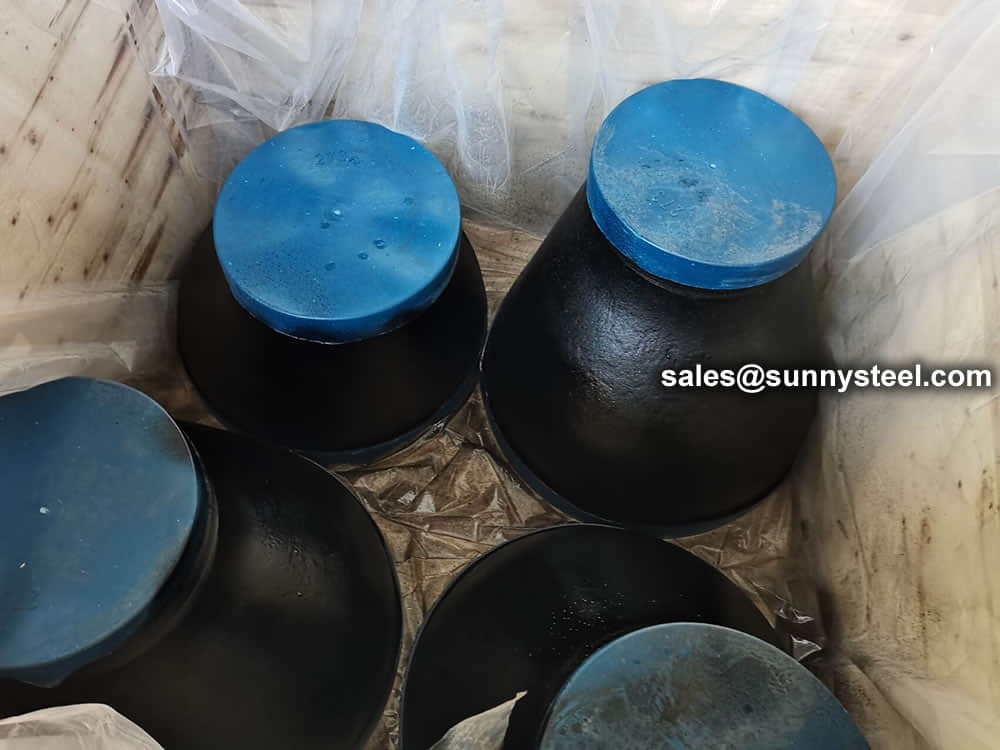
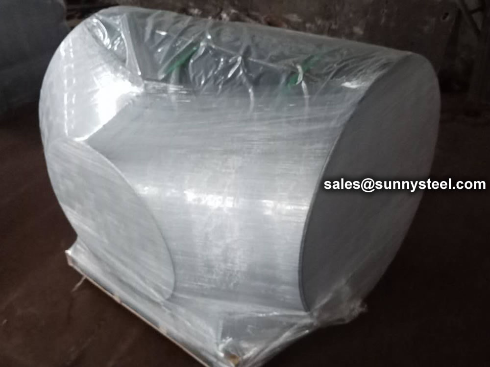
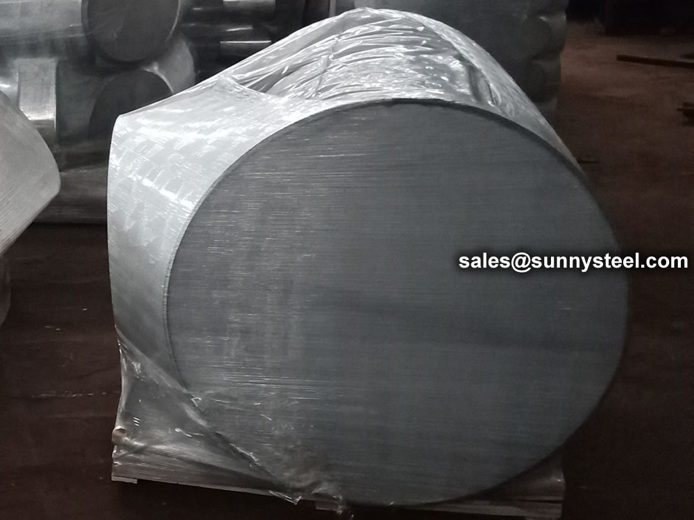
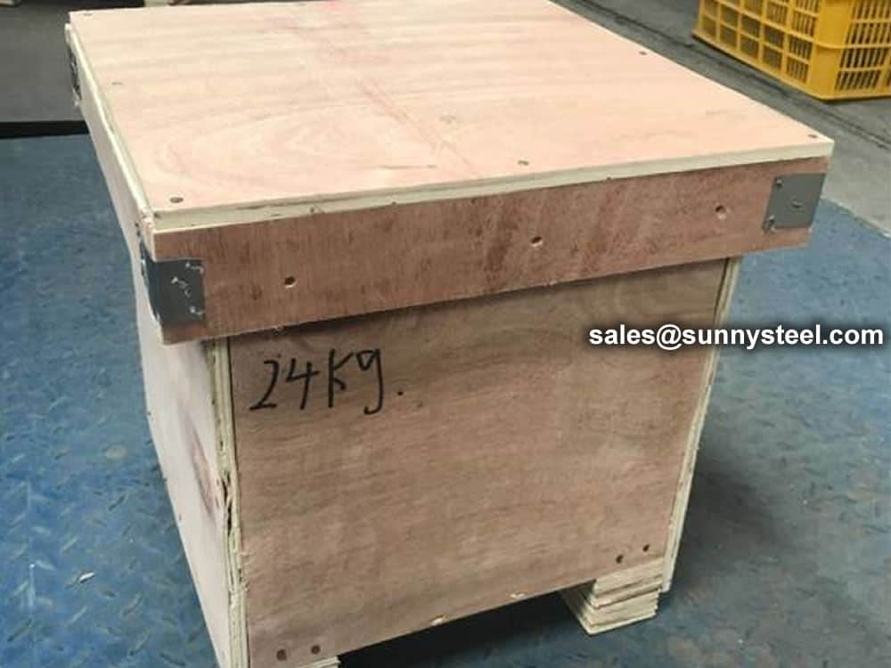
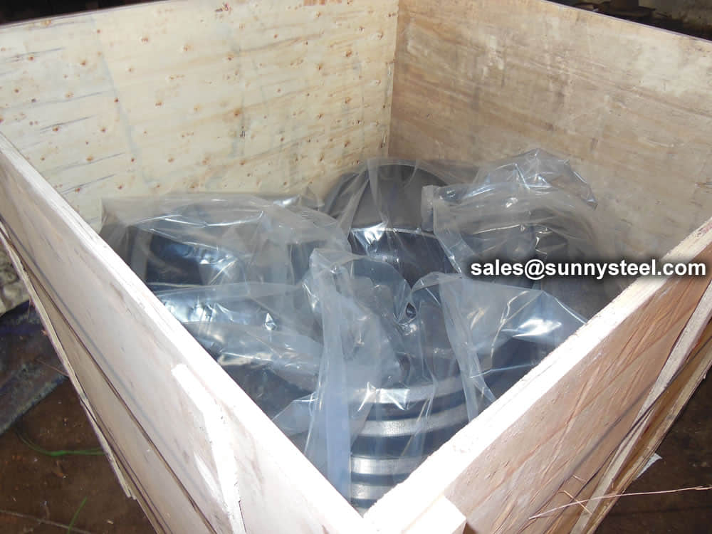
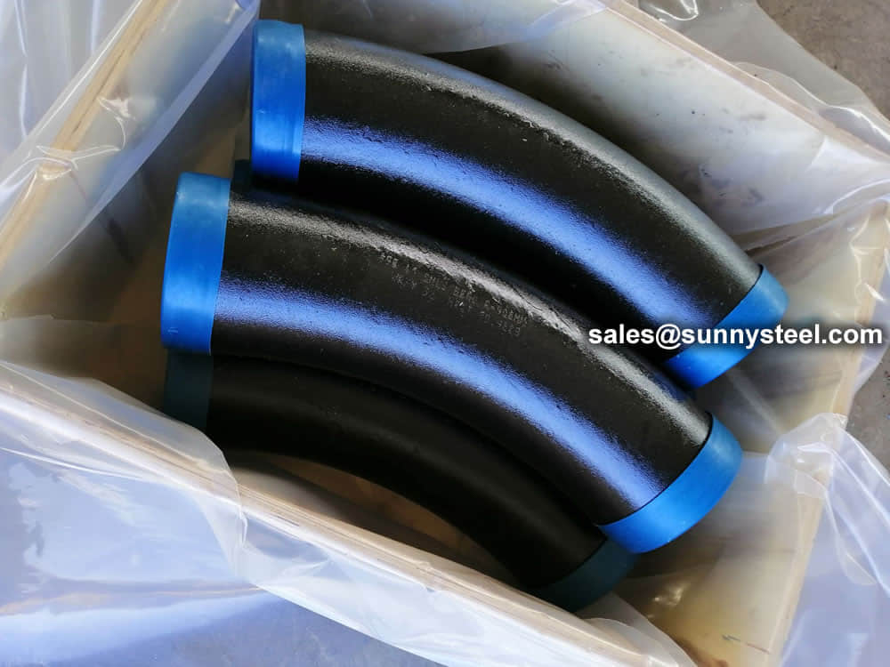
For packing of carbon steel flanges with painting,we would use the bubble wrap to protect the painting.For flanges without painting or oiled with long-term shipment,we would suggest client to use the anti-tarnish paper and plastic bag to prevent the rust.
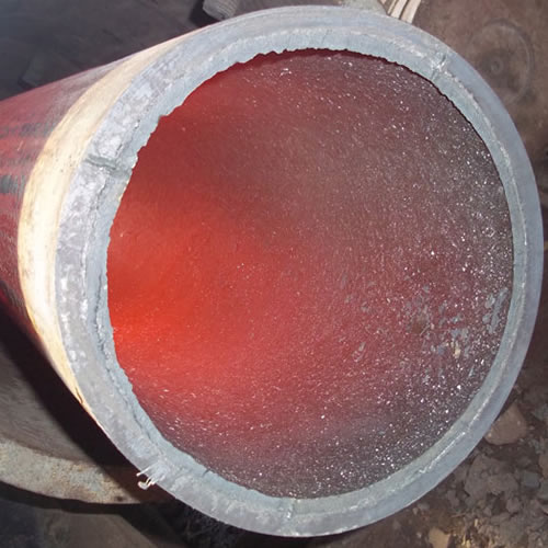
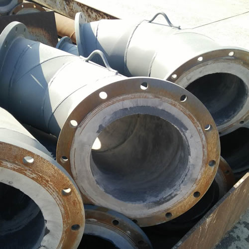
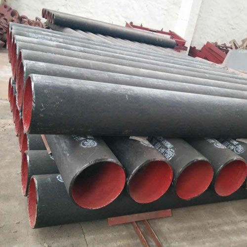
Ceramic lined pipe is made through self-propagating high-temperature synthesis (SHS) technique.
Cast basalt lined steel pipe is composed by lined with cast basalt pipe, outside steel pipe and cement mortar filling between the two layers.
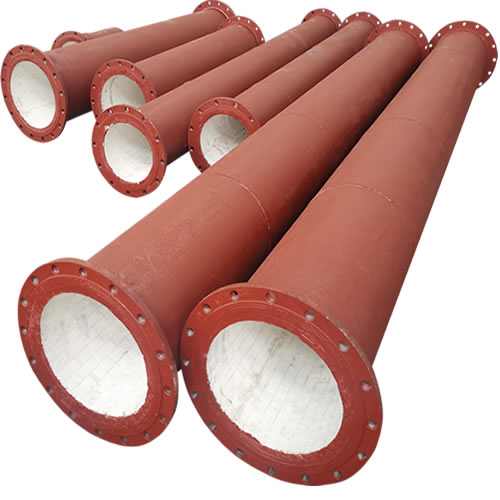
Ceramic tile lined pipes have very uniform coating of specially formulated ceramic material that is affixed to the inner of the pipe.
The material of the rare earth alloy wear-resistant pipe is ZG40CrMnMoNiSiRe, which is also the grade of rare earth alloy steel.
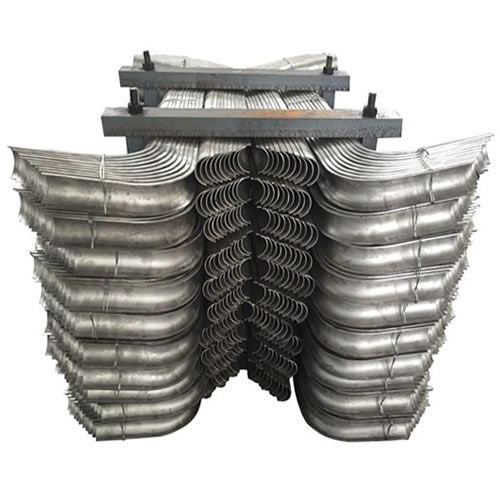
Tubes Erosion Shields are used to protect boiler tubing from the highly erosive effects of high temperatures and pressures thereby greatly extending tube life.
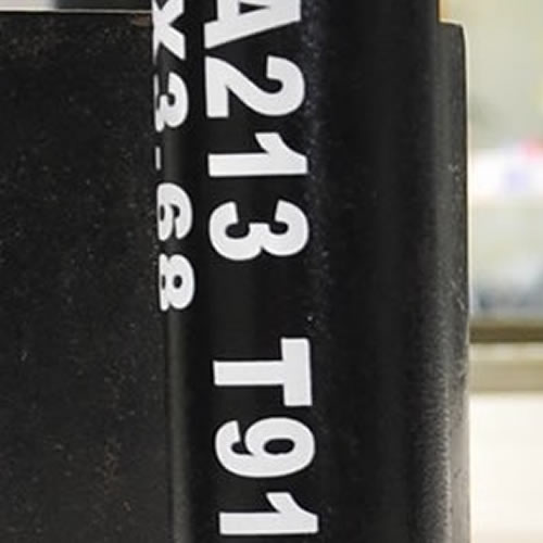
The ASTM A213 T91 seamless tubes are primarily used for boiler, superheater, and heat-exchanger.

When you partner with Sunny Steel, you can stop worrying about meeting deadlines thanks to our responsive and timely service. You'll also say goodbye to unnecessary shopping around. Instead, you'll get white glove service from an expert who understands your needs and can get you the materials you need quickly.