5D Bend Pipe
The radius of a 5D pipe bend is actually what is 5 times the nominal diameter.
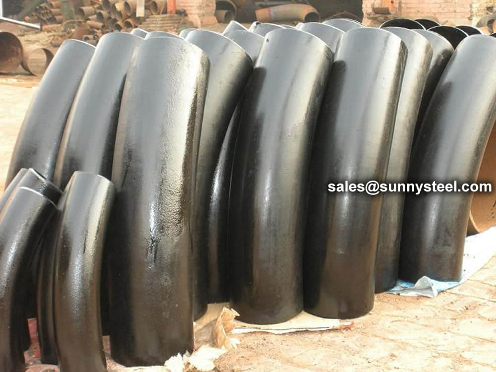
A 3D bend is a bend in which the radius of the curve is equal to 3 times the diameter of the pipe.
A tube can be bent in several angels and directions. However, some of the most common and simple bends include the formation of an elbow that ranges from two degrees 90 degrees.
A 3D bend is a bend in which the radius of the curve is equal to 3 times the diameter of the pipe. It is a smoother bend than a 1.5D bend, which looks almost like a regular 90-degree right angle, but it is a sharper bend than a 5D bend, which looks like a smooth arc between two perpendicular pieces. 3D pipe bending refers to the process of bending pipes or tubes in three dimensions, allowing for complex and custom-shaped bends.
Here are a few of the places where you will commonly find 3D bends being used:
3D pipe bending is a pipe bend that the bend radius is 3 times the pipe outside diameter. The RADIUS of a 5D pipe bend is actually what is 5 times the nominal diameter. So if you had a 10″ diameter pipe, the radius of the centerline of the bend would be 50 inches. Larger numbers have smoother curves.
3D Bend is bend radius 3 times of the pipe outside diameter, for example if a 3D pipe bend used in a 10 inch pipelines, the bending radius would be 30 inches. Same with elbow (1D or 1.5D), 3D bend also ranges different degrees like 45 degree, 60 Degree and 90 Degree.
3D pipe bending involves using specialized equipment and machines to form pipes into various shapes and curves along three planes. This technique is commonly used in industries such as aerospace, automotive, and construction to create complex piping systems for various applications. 3D pipe bends allow for more efficient and effective use of space while improving fluid flow and reducing the risk of leaks or breaks.
3D bends are pipe bends whose radius is three times the outside diameter of the pipe. Others are the U-bends that have a bend of 180 degrees. In any project using metal pipes, there are likely to be a few places where the pipe has to go around a corner, or has to be bent to follow a certain contour. In many cases, with proper planning and a good design, these bends can be made using pre-fabricated elbows, which come in popular angles like 45 or 90 degrees and several common bend radii, typically referred to as either short or long-radius bends.
Sometimes, however, a custom bend will be required to make the pipe fit precisely around an obstacle or to follow a curve perfectly. Pipe can be custom-bent with presses or more complex machines using one of several common methods, including ram bending, rotary draw bending, compression bending and three roll bending, among others. Separate dies are typically required for each size of pipe and each different bend radius, except on more complex machines.
A 3D bend is a bend in which the radius of the curve is equal to 3 times the diameter of the pipe. It is a smoother bend than a 1.5D bend, which looks almost like a regular 90-degree right angle, but it is a sharper bend than a 5D bend, which looks like a smooth arc between two perpendicular pieces.
We specialize in bending, fabricating and testing of heating and cooling coils. We are proud of our leading reputation in the industry with our attitude of professional workmanship and on-time delivery. Some of our advantages over competitors include:
Sunny Steel fabricates all types and sizes of cooling coils from 1/8″ pipe to 8″ pipe and all alloys.
There is no difference between 3R and 3D.
Larger numbers have smoother curves.
However, some of the most common and simple bends include the formation of an elbow that ranges from two degrees 90 degrees. Others are the U-bends that have a bend of 180 degrees.
The process involves the use of machines and mechanical force. Normally, pipe or tube bending machines are human powered, hydraulic assisted, or even pneumatic powered. The following are some of the most commonly used pipe bending processes.
This is one of the most commonly used processes. It is used to come up with bending geometrics that include multiple plane bending curves. Normally, the profile is led through a bending roll and the supporting roll or even rolls, while at the same time being pushed through the tool. The bending radius is normally determined by the position of the forming radius. This is one of the most flexible processes used in the creation of bends, for multiple radii can be actually obtained.
This is one of the most precise technologies used to create 3D bends. It uses a feature called ‘die sets’ that has a constant center line radius. Rotary draw benders can be programmed to store several bend works with different degrees when it comes to bending. Technically, an IDX (positioning index table) is at all times attached to the rotary bender. This enables the operator to create complex bends that have varying planes. Rotary benders are largely used in tube bending.
When it comes to this bend tubing process, an induction coil is normally placed at the bend point of the pipe. thereafter, the area is subjected to temperatures ranging from 800 to 2200 degrees Celsius. When it is hot, pressure is actually applied to bend the pipe. Finally, the pipe can be passed through cold air or water. Normally, this process is used in extremely large pipes such as gas pipes lines
In this process, the pipe is filled with sand and the ends caped. The pipe is then passed through a furnace with temperature of 870 degrees Celsius. thereafter, the pipe is placed on the slab and the pins set in it. You can then bent the pipe around the pins using a tool such as the winch, or you can even apply some mechanical force. The sand that is normally put in the pipe minimizes any distortion in the cross section of the pipe.
This will probably be one of the first processes used on cold tubing and even pipes. Normally, a die is pressed against the pipe. This will force the pipe to fit the shapes. However, this process comes with its own drawbacks since the internal area is not supported. It results in some kind of deformation and perfect 3D bends and 5D bends will not be achieved.

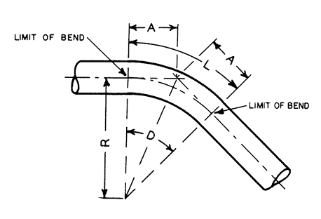
Diagram of ASME B16.49 induction bend, 90° 3D Bend with Tangent lengths.
Larger radius bends offer several advantages for fluid flow in pipes. They provide smoother flow for various mediums such as water, slurry, oils, solids, and more. This reduced resistance results in improved flow efficiency compared to 1D or 1.5D bends. Additionally, longer bend radii help minimize turbulence, especially when compared to standard fittings.
When planning your piping project, it's essential to assess whether traditional 1D or 1.5D bends can effectively meet your requirements. If there are any doubts, it's advisable to consider using 3D or 5D bends to optimize your system's performance.
The bend is used to change the direction of run of pipe.it advantage is can matach long distance transition requirements,so it is commonly that bends dimension according to customer design.
Formula:L = R x BL = Length of pipe requiredR = Radius of bendB = Constant from table used to find “L”L =30 x 1.5705 =47.115 in.or 47-1/8”
Standards accord to:
Pressure: SCH5 to SCH160
Bending radius(R): R=3D, 5D, 7D and 12D
Bending angle (θ):15°, 30°, 45°, 60°, 90°, 135°, 180°
Outer diamete(D): D≤1800mm
Wall thickness(T): T≤120mm
Straight Length (L): The length between two ends general from 300mm-1500mm
Example: Find the length of pipe required to make a 90 bend with a radius of 30"
| Nominal pipe | Outside Diameter at Bevel | Center to End | ||||
|---|---|---|---|---|---|---|
| DN size | D1 | D2 | C | M | ||
| Series A | Series B | Series A | Series B | |||
| 20×15 | 26.9 | 25 | 21.3 | 18 | 29 | 29 |
| 25×20 | 33.7 | 32 | 26.9 | 25 | 38 | 38 |
| 25×15 | 33.7 | 32 | 21.3 | 18 | 38 | 38 |
| 32×25 | 42.4 | 38 | 33.7 | 32 | 48 | 48 |
| 32×20 | 42.4 | 38 | 26.9 | 25 | 48 | 48 |
| 32×15 | 42.4 | 38 | 21.3 | 18 | 48 | 48 |
| 40×32 | 48.3 | 45 | 42.4 | 38 | 57 | 57 |
| 40×25 | 48.3 | 45 | 33.7 | 32 | 57 | 57 |
| 40×20 | 48.3 | 45 | 26.7 | 25 | 57 | 57 |
| 40×15 | 48.3 | 45 | 21.3 | 18 | 57 | 57 |
| 50×40 | 60.3 | 57 | 48.3 | 45 | 64 | 60 |
| 50×32 | 60.3 | 57 | 42.4 | 38 | 64 | 57 |
| 50×25 | 60.3 | 57 | 33.7 | 32 | 64 | 51 |
| 50×20 | 60.3 | 57 | 26.9 | 25 | 64 | 44 |
| 65×50 | 76.1(73) | 76 | 60.3 | 57 | 76 | 70 |
| 65×40 | 76.1(73) | 76 | 48.3 | 45 | 76 | 67 |
| 65×32 | 76.1(73) | 76 | 42.4 | 38 | 76 | 64 |
| 65×25 | 76.1(73) | 76 | 33.7 | 32 | 76 | 57 |
| 80×65 | 88.9 | 89 | 76.1(73) | 76 | 86 | 83 |
| 80×50 | 88.9 | 89 | 60.3 | 57 | 86 | 76 |
| 80×40 | 88.9 | 89 | 48.3 | 45 | 86 | 73 |
| 80×32 | 88.9 | 89 | 42.4 | 38 | 86 | 70 |
| 90×80 | 101.6 | - | 88.9 | - | 95 | 92 |
| 90×65 | 101.6 | - | 76.1(73) | - | 95 | 89 |
| 90×50 | 101.6 | - | 60.3 | - | 95 | 83 |
| 90×40 | 101.6 | - | 48.3 | - | 95 | 79 |
| 100×90 | 114.3 | - | 101.6 | - | 105 | 102 |
| 100×80 | 114.3 | 108 | 88.9 | 89 | 105 | 98 |
| 100×65 | 114.3 | 108 | 76.1(73) | 76 | 105 | 95 |
| 100×50 | 114.3 | 108 | 60.3 | 57 | 105 | 89 |
| 100×40 | 114.3 | 108 | 48.3 | 45 | 105 | 86 |
| 125×100 | 139.7 | 133 | 114.3 | 108 | 124 | 117 |
| 125×90 | 139.7 | - | 101.6 | - | 124 | 114 |
| 125×80 | 139.7 | 133 | 88.9 | 89 | 124 | 111 |
| 125×65 | 139.7 | 133 | 76.1(73) | 76 | 124 | 108 |
| 125×50 | 133 | 60.3 | 57 | 124 | 105 | |
| 150×125 | 168.3 | 159 | 139.7 | 133 | 143 | 137 |
| 150×100 | 168.3 | 159 | 114.3 | 108 | 143 | 130 |
| 150×90 | 168.3 | - | 101.6 | - | 143 | 127 |
| 150×80 | 168.3 | 159 | 88.9 | 89 | 143 | 124 |
| 150×65 | 168.3 | 159 | 76.1(73) | 76 | 143 | 121 |
| 200×150 | 219.1 | 219 | 168.3 | 159 | 178 | 168 |
| 200×125 | 219.1 | 219 | 139.7 | 133 | 178 | 162 |
| 200×100 | 219.1 | 219 | 114.3 | 108 | 178 | 156 |
| 200×90 | 219.1 | - | 101.6 | - | 178 | 152 |
| 200×200 | 273 | 273 | 219.1 | 219 | 216 | 208 |
| 200×150 | 273 | 273 | 168.3 | 159 | 216 | 194 |
| 200×125 | 273 | 273 | 139.7 | 133 | 216 | 191 |
| 200×100 | 273 | 273 | 114.3 | 108 | 216 | 184 |
| 300×250 | 323.9 | 325 | 273 | 273 | 254 | 241 |
| 300×200 | 323.9 | 325 | 219.1 | 219 | 254 | 229 |
| 300×150 | 323.9 | 325 | 168.3 | 159 | 254 | 219 |
| 300×125 | 323.9 | 325 | 139.7 | 133 | 254 | 216 |
| 350×300 | 355.6 | 377 | 323.9 | 325 | 279 | 270 |
| 350×250 | 355.6 | 377 | 273 | 273 | 279 | 257 |
| 350×200 | 355.6 | 377 | 219.1 | 219 | 279 | 248 |
| 350×150 | 355.6 | 377 | 168.3 | 159 | 279 | 238 |
| 400×350 | 406.4 | 426 | 355.6 | 377 | 305 | 305 |
| 400×300 | 406.4 | 426 | 323.9 | 325 | 305 | 295 |
| 400×250 | 406.4 | 426 | 273 | 273 | 305 | 283 |
| 400×200 | 406.4 | 426 | 219.1 | 219 | 305 | 273 |
| 400×150 | 406.4 | 426 | 168.3 | 159 | 305 | 264 |
| 450×400 | 457.2 | 478 | 406.4 | 426 | 343 | 330 |
| 450×350 | 457.2 | 478 | 355.6 | 377 | 343 | 330 |
| 450×300 | 457.2 | 478 | 323.9 | 325 | 343 | 321 |
| 450×250 | 457.2 | 478 | 273 | 273 | 343 | 308 |
| 450×200 | 457.2 | 478 | 219.1 | 219 | 343 | 298 |
| 500×450 | 508 | 529 | 457.2 | 478 | 381 | 368 |
| 500×100 | 508 | 529 | 406.4 | 426 | 381 | 356 |
| 500×350 | 508 | 529 | 355.6 | 377 | 381 | 356 |
| 500×300 | 508 | 529 | 323.9 | 325 | 381 | 346 |
| 500×250 | 508 | 529 | 273 | 273 | 381 | 333 |
| 500×200 | 508 | 529 | 219.1 | 219 | 381 | 324 |
| 550×500 | 559 | - | 508 | - | 419 | 406 |
| 550×450 | 559 | - | 457 | - | 419 | 394 |
| 550×400 | 559 | - | 406 | - | 419 | 381 |
| 600×550 | 610 | - | 559 | - | 432 | 432 |
| 600×550 | 610 | 630 | 508 | 530 | 432 | 432 |
| 600×450 | 610 | 630 | 457 | 480 | 432 | 419 |
| 650×600 | 660 | - | 610 | - | 495 | 483 |
| 650×550 | 660 | - | 559 | - | 495 | 470 |
| 650×500 | 660 | - | 508 | - | 495 | 457 |
| 700×650 | 711 | - | 660 | - | 521 | 521 |
| 700×600 | 711 | 720 | 610 | 630 | 521 | 508 |
| 700×550 | 711 | - | 559 | - | 521 | 495 |
| 750×700 | 762 | - | 711 | - | 559 | 546 |
| 750×650 | 762 | - | 660 | - | 559 | 546 |
| 750×600 | 762 | - | 610 | - | 559 | 533 |
| 800×750 | 813 | - | 762 | - | 597 | 584 |
| 800×700 | 813 | 820 | 711 | 720 | 597 | 572 |
| 800×650 | 813 | - | 660 | - | 597 | 572 |
| 850×800 | 864 | - | 813 | - | 635 | 622 |
| 850×750 | 864 | - | 762 | - | 635 | 610 |
| 850×700 | 864 | - | 711 | - | 635 | 597 |
| 900×850 | 914 | - | 864 | - | 673 | 660 |
| 900×800 | 914 | 920 | 813 | 820 | 673 | 648 |
| 900×750 | 914 | - | 762 | - | 673 | 635 |
| 950×900 | 965 | - | 914 | - | 711 | 711 |
| 950×850 | 965 | - | 864 | - | 711 | 698 |
| 950×800 | 965 | - | 813 | - | 711 | 686 |
| 1000×950 | 1016 | - | 965 | - | 749 | 749 |
| 1000×900 | 1016 | 1020 | 914 | 920 | 749 | 737 |
| 1000×8500 | 1016 | - | 864 | - | 749 | 724 |
| 1000×1000 | 1067 | - | 1016 | - | 762 | 711 |
| 1050×950 | 1067 | - | 965 | - | 762 | 711 |
| 1050×900 | 1067 | - | 914 | - | 762 | 711 |
| 1100×1050 | 1118 | - | 1067 | - | 813 | 762 |
| 1100×1000 | 1118 | 1120 | 1016 | 1020 | 813 | 749 |
| 1100×950 | 1118 | - | 965 | - | 813 | 737 |
| 1150×1100 | 1168 | - | 1118 | - | 851 | 800 |
| 1150×1050 | 1168 | - | 1067 | - | 851 | 787 |
| 1150×1000 | 1168 | - | 1016 | - | 851 | 775 |
| 1200×1150 | 1220 | - | 1168 | - | 889 | 838 |
| 1200×1100 | 1220 | 1220 | 1118 | 1120 | 889 | 838 |
| 1200×1050 | 1220 | - | 1067 | - | 889 | 813 |
Just before the final delivery, our merchandise are stringently checked by a team of quality analyzers on varied parameters, which guarantee their flawlessness and durability. In addition, clients can avail these goods from us at competitive rates.
Pipe bends play a vital role in flow control systems, allowing the smooth and efficient redirection of fluids and gases. These components are designed to change the direction of piping systems, allowing the fluid or gas to flow around obstacles or corners with minimal turbulence or pressure loss. By minimising friction and pressure drop, pipe bends help maintain optimum flow rates, reduce energy consumption and improve overall system performance.
Pipe fittings are necessary to join together pipes, or to change the direction of an existing pipe. Pipes and pipe fittings are made of a variety of materials, depending on the fluid or gas being transported. Most pipe fittings tend to be either threaded or able to slip over the pipes they connect. Whether you are using steel pipes of PVC pipes, a chemical solvent is required to create a seal between the pipe and the fittings.
Measure the required length of the pipe to be installed, keeping in mind the extra length required where the pipe will be inserted into the fitting. Mark this length on the pipe.
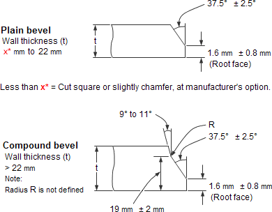
The ends of all buttweld fittings are bevelled, exceeding wall thickness 4 mm for austenitic stainless steel, or 5 mm for ferritic stainless steel. The shape of the bevel depending upon the actual wall thickness. This bevelled ends are needed to be able to make a “Butt weld”.
Welding Bevel acc.to ASME / ANSI B16.9 and ASME / ANSI B16.28
ASME B16.25 covers the preparation of buttwelding ends of piping components to be joined into a piping system by welding. It includes requirements for welding bevels, for external and internal shaping of heavy-wall components, and for preparation of internal ends (including dimensions and dimensional tolerances).
Our in-hourse R&D team developed bevel ends equipment are good using in thickness 2mm to 20mm pipe fittings, guarantee high efficiency and high quality.
These weld edge preparation requirements are also incorporated into the ASME standards (e.g., B16.9, B16.5, B16.34).
ASME B16.25 sets standards for the preparation of the ends of components that need to be welded together.
Cut square or slight chamfer, at manufacturer’s option for :
A pipe fitting is defined as a part used in a piping system, for changing direction, branching or for change of pipe diameter, and which is mechanically joined to the system.
There are many different types of fittings and they are the same in all sizes and schedules as the pipe.
ASME B16.9 Standard covers overall dimensions, tolerances,ratings, testing, and markings for factory-made wrought buttwelding fittings in sizes NPS 1⁄2 through NPS 48 (DN 15 through DN 1200).
Download PDF| Nominal | Outside Diameter | 90° Elbows | 45° Elbows | 180° Returns | ||||
|---|---|---|---|---|---|---|---|---|
| Pipe Size |
Long Radius | Short Radius | Long Radius | Long Radius | ||||
| (inches) | (mm) | (inches) | Center to Face | Center to Face | Center to Face | Radius | Center to Center | Back to face |
| (inches) | (inches) | (inches) | (inches) | (inches) | (inches) | |||
| 1/2 | 21.3 | 0.84 | 1.5 | – | 5/8 | 2 | 1.875 | |
| 3/4 | 26.7 | 1.05 | 1.125 | – | 7/16 | 2.25 | 1.6875 | |
| 1 | 33.4 | 1.315 | 1.5 | 1 | 7/8 | 3 | 2.1875 | |
| 1.25 | 42.2 | 1.66 | 1.875 | 1.25 | 1 | 3.75 | 2.75 | |
| 1.5 | 48.3 | 1.9 | 2.25 | 1.5 | 1.125 | 3 | 4.5 | 3.25 |
| 2 | 60.3 | 2.375 | 3 | 2 | 1.375 | 4 | 6 | 4.1875 |
| 2.5 | 73 | 2.875 | 3.75 | 2.5 | 1.75 | 5 | 7.5 | 5.1875 |
| 3 | 88.9 | 3.5 | 4.5 | 3 | 2 | 6 | 9 | 6.25 |
| 3.5 | 101.6 | 4 | 5.25 | 3.5 | 2.25 | 7 | 10.5 | 7.25 |
| 4 | 114.3 | 4.5 | 6 | 4 | 2.5 | 8 | 12 | 8.25 |
| 5 | 141.3 | 5.563 | 7.5 | 5 | 3.125 | 10 | 15 | 10.3125 |
| 6 | 168.3 | 6.625 | 9 | 6 | 3.75 | 12 | 18 | 12.3125 |
| 8 | 219.1 | 8.625 | 12 | 8 | 5 | 12 | 24 | 16.3125 |
| 10 | 273.1 | 10.75 | 15 | 10 | 6.25 | 15 | 30 | 20.375 |
| 12 | 323.9 | 12.75 | 18 | 12 | 7.5 | 18 | 36 | 24.375 |
| NOMINAL PIPE SIZE NPS | ANGULARITY TOLERANCES | ANGULARITY TOLERANCES |
|---|---|---|
| Size | Off Angle Q | Off Plane P |
| ½ to 4 | 0.03 | 0.06 |
| 5 to 8 | 0.06 | 0.12 |
| 10 to 12 | 0.09 | 0.19 |
| 14 to 16 | 0.09 | 0.25 |
| 18 to 24 | 0.12 | 0.38 |
| 26 to 30 | 0.19 | 0.38 |
| 32 to 42 | 0.19 | 0.5 |
| 44 to 48 | 0.18 | 0.75 |
All dimensions are given in inches. Tolerances are equal plus and minus except as noted.
The ASME B16.9 pipe fittings can be used under the jurisdiction of the ASME Boiler & Pressure Vessel Code (BPVC) as well as the ASME Code for pressure piping. Referencing pressure ratings of flanges per ASME B16.5, they can be designated as Classes 150, 300, 600, 900, 1500 and 2500. The allowable pressure ratings for ASME B16.9 pipe fittings may be calculated as for straight seamless pipe of equivalent material in accordance with the rules established in the applicable sections of ASME B31 Code for pressure piping.
The design of butt welding pipe fittings made to ASME B16.9 shall be established by one of the following methods: (a) mathematical analyses contained in pressure vessel or piping codes; (b) proof testing; (c) experimental stress analysis with hydrostatic testing to validate experimental results; (d) detailed stress analysis with results evaluation.
Generally, ASME B16.9 pipe fittings shall be marked to show the following details: “trademark + material grade + wall thickness + size + heat number”. For example, “M ASTM A234 WP5 SCH80 6″ 385“. When steel stamps are used, care shall be taken so that
the marking is not deep enough or sharp enough to cause cracks or to reduce the wall thickness of the fitting below the minimum allowed.
The ASME B16.9 fittings may be made from an extensive range of mateirals covering (1) carbon and low-alloy steels in accordance with ASTM A234 and ASTM A420; (2) austenitic and duplex stainless steels in accordance with ASTM A403 and ASTM A815; (3) nickel alloys in accordance with ASTM B366; (4) aluminum alloys in accordance with ASTM B361; and (5) titanium alloys in accordance with ASTM B363.

Sizes 1/2″ – 48″

In any project using metal pipes, there are likely to be a few places where the pipe has to go around a corner, or has to be bent to follow a certain contour. In many cases, with proper planning and a good design, these bends can be made using pre-fabricated elbows, which come in popular angles like 45 or 90 degrees and several common bend radii, typically referred to as either short or long-radius bends.
Sometimes, however, a custom bend will be required to make the pipe fit precisely around an obstacle or to follow a curve perfectly. Pipe can be custom-bent with presses or more complex machines using one of several common methods, including ram bending, rotary draw bending, compression bending and three roll bending, among others. Separate dies are typically required for each size of pipe and each different bend radius, except on more complex machines.
A 3D bend is a bend in which the radius of the curve is equal to 3 times the diameter of the pipe. It is a smoother bend than a 1.5D bend, which looks almost like a regular 90-degree right angle, but it is a sharper bend than a 5D bend, which looks like a smooth arc between two perpendicular pieces.
Here are a few of the places where you will commonly find 3D bends being used:
Both manufacturer-supplied and custom exhaust systems for cars and trucks often feature a wide assortment of bends to maneuver around various obstacles on the underside of the car, such as the engine, transmission, cross-members and the fame. Most vehicle exhausts feature custom compound beds, and the fabricators generally prefer smoother curves, like 3D bends or even 5D bends, because they reduce the turbulence and back-pressure inside the exhaust system, and that can help increase an engine’s performance.
Off-roading can be a very competitive sport, or, more simply, an expensive hobby. One of the many dangers when rock-crawling, mudding or generally pushing a vehicle beyond its limits, is the possibility of rolling the vehicle over. To prevent injury and damage to the vehicle, a quality roll cage is an absolute necessity. Many roll cages are custom formed from metal pipe, often chromoly steel, using an assortment of bends, including the common 3D bend. Each piece is bent, cut and welded together to make a complete roll cage that is both durable and aesthetically pleasing.
3D bends are very common in structural frames of all kinds. These can range from the frames of custom automobiles, to the frames of buildings, or even airplanes or spacecraft. Often, to build a structural frame, pipe is bent, cut and welded together to make a strong skeleton, and then sheet metal is attached via screws or welds to create a completed assembly, which is both extremely strong and resistant to the elements. When built using aluminum, titanium or certain alloys, it can also be lightweight and corrosion-resistant.
Many types of furniture incorporate tubular steel and 3D bends for either structural or aesthetic purposes. Tables frequently use tubular steel legs, with bends where they meet the tabletop to provide support. Metal chairs, couches and futons with tubular frames often use similar bends to provide a nice gentle curve that is both pleasing to the eye and structurally rigid. Shelving units can also incorporate custom bends, either for decoration or for structural integrity.
The 3D bend is also quite common in fencing, for both decorative and structural uses. It is seen extensively in galvanized chain-link fencing, especially to add a gentle curve to gates and other decorative items, or in custom-designed fencing. Pipe is also used regularly in fencing for cattle, horses and other livestock, as well as for domestic pets, and often decorative touches are added that require custom bends.
In the plumbing industry, 3D bends are quite common. They are incorporated anywhere that standard elbows cannot be relied upon to bypass obstacles or to change the angle of the pipe. In pipes that contain high-viscosity liquids or fluids that require reduced turbulence, the smoother 3D bend is often preferable to sharper bends. Custom bends are used in plumbing of all kinds, from the pipes in your home, to the pipes in chemical plants, food processors or refineries.
Wiring conduit is designed to protect electrical cables from the weather, accidental damage and other dangers. When wiring conduit is required on an electrical job, often it must be bent to go around corners or other obstacles. Typically, smoother curves like 3D or 5D bends are used instead of sharp curves, because it makes it much easier to fish the wire through the conduit after it is installed. Electricians usually carry their own tools to bend small-diameter conduit, though for larger-diameter versions, they may require custom bending services.
Gas and oil pipelines, like any plumbing system, often use 3D bends in many places along their lengths. Unlike typical household pipes, however, these are typically much larger, and require some serious machinery to do custom bends. Gentle bends help the high-viscosity oil flow through the pipes easier, and they help natural gas flow smoother, reducing pipe fatigue and the chance of leaks.
An often-overlooked area where 3D bends are used is in the hand rails for stairways or walkways, as well as the safety rails used to provide handicap access. Custom bends are often used to follow curves, go around corners or to provide mounting points at each end of the pipe. Sometimes the bends are also used strictly for decorative purposes.
In many art projects, tubular steel is used to create a frame, upon which the artist builds the rest of the piece. Custom bends are often used to create gentle-flowing lines and other aesthetic features, which many times are covered up by other materials. The frame creates a strong base for the rest of the piece, and determines its overall shape.
If you have a project that calls for 3D bends, it often may not be feasible to buy the equipment to produce them yourself. The tools can be prohibitively expensive, and they require a significant amount of training and practice to operate them properly. Fortunately, there are services available that will custom-bend pipe to your exact specifications, saving you the expense and the hassle of buying your own equipment.
Pipe fitting dimensions are in either metric or Standard English.
Because pipe fitting covers Pipe Fitting Dimensions several aspects, only the most common pipe fitting sizes can be given here. The most applied version is the 90° long radius and the 45° elbow, while the 90° short radius elbow is applied if there is too little space. The function of a 180° elbow is to change direction of flow through 180°. Both, the LR and the SR types have a center to center dimension double the matching 90° elbows. These fittings will generally be used in furnesses or other heating or cooling units.
Some of the standards that apply to buttwelded fittings are listed below. Many organizations such as ASME, ASTM, ISO, MSS, etc. have very well developed standards and specifications for buttwelded fittings. It is always up to the designer to ensure that they are following the applicable standard and company specification, if available, during the design process.
Some widely used pipe fitting standards are as follows:
This is one of the reputed organizations in the world developing codes and standards.
The schedule number for pipe fitting starts from ASME/ANSI B16. The various classifications of ASME/ANSI B16 standards for different pipe fittings are as follows:
This is one of the largest voluntary standards development organizations in the world. It was originally known as the American Society for Testing and Materials (ASTM).
AWWA About – Established in 1881, the American Water Works Association is the largest nonprofit, scientific and educational association dedicated to managing and treating water, the world’s most important resource.
ANSI is a private, non-profit organization. Its main function is to administer and coordinate the U.S. voluntary standardization and conformity assessment system. It provides a forum for development of American national standards. ANSI assigns “schedule numbers”. These numbers classify wall thicknesses for different pressure uses.
The Manufacturers Standardization Society (MSS) of the Valve and Fittings Industry is a non-profit technical association organized for development and improvement of industry, national and international codes and standards for: Valves, Valve Actuators, Valve Modification, Pipe Fittings, Pipe Hangers, Pipe Supports, Flanges and Associated Seals
Piping codes imply the requirements of design, fabrication, use of materials, tests and inspection of various pipe and piping system. It has a limited jurisdiction defined by the code. On the other hand, piping standards imply application design and construction rules and requirements for pipe fittings like adapters, flanges, sleeves, elbows, union, tees, valves etc. Like a code, it also has a limited scope defined by the standard.
“Standards” on pipe fittings are based on certain factors like as follows:
BSP is the U.K. standard for pipe fittings. This refers to a family of standard screw thread types for interconnecting and sealing pipe ends by mating an external (male) with an internal (female) thread. This has been adopted internationally. It is also known as British Standard Pipe Taper threads (BSPT )or British Standard Pipe Parallel (Straight) threads (BSPP ). While the BSPT achieves pressure tight joints by the threads alone, the BSPP requires a sealing ring.
This is the Japanese industrial standards or the standards used for industrial activities in Japan for pipe, tube and fittings and published through Japanese Standards Associations.
National Pipe Thread is a U.S. standard straight (NPS) threads or for tapered (NPT) threads. This is the most popular US standard for pipe fittings. NPT fittings are based on the internal diameter (ID) of the pipe fitting.
We are manufacturer of Flange bolts & Nuts and supply high quality
The AN standard was originally designed for the U.S. Military. Whenever, a pipe fitting is AN fittings, it means that the fittings are measured on the outside diameter of the fittings, that is, in 1/16 inch increments.
For example, an AN 4 fitting means a fitting with an external diameter of approximately 4/16″ or ¼”. It is to be noted that approximation is important because AN external diameter is not a direct fit with an equivalent NPT thread.
Dash size is the standard used to refer to the inside diameter of a hose. This indicates the size by a two digit number which represents the relative ID in sixteenths of an inch. This is also used interchangeably with AN fittings. For example, a Dash “8” fitting means an AN 8 fitting.
ISO is the industrial pipe, tube and fittings standards and specifications from the International Organization for Standardization. ISO standards are numbered. They have format as follows:
“ISO[/IEC] [IS] nnnnn[:yyyy] Title” where
| Standard | Specification |
|---|---|
| ASTM A234 | Standard Specification for Piping Fittings of Wrought Carbon Steel and Alloy Steel for Moderate and High Temperature Service |
| ASTM A420 | Standard Specification for Piping Fittings of Wrought Carbon Steel and Alloy Steel for Low-Temperature Service |
| ASTM A234 WPB | ASTM A234 WPB refers to a specific grade of carbon steel pipe fittings, which are widely used in pressure piping and pressure vessel fabrication for service at moderate and elevated temperatures. |
| ASME B16.9 | ASME B16.9 Standard covers overall dimensions, tolerances,ratings, testing, and markings for factory-made wrought buttwelding fittings in sizes NPS 1⁄2 through NPS 48 (DN 15 through DN 1200). |
| ASME B16.28 | ASME B16.28 Standard covers ratings, overall dimensions, testing, tolerances, and markings for wrought carbon and alloy steel buttwelding short radius elbows and returns. |
| MSS SP-97 | MSS SP-97 Standard Practice covers essential dimensions, finish, tolerances, testing, marking, material, and minimum strength requirements for 90 degree integrally reinforced forged branch outlet fittings of buttwelding, socket welding, and threaded types. |
| ASTM A403 | Standard Specification for Wrought Austenitic Stainless Steel Piping Fittings. |
| DIN | EN | ASME |
|---|---|---|
| St 35.8 I St 35.8 III 15 Mo 3 13 CrMo 4 4 10 CrMo 9 10 St 35 N St 52.0 St 52.4 |
P235GH-TC1 P235GH-TC2 16Mo3 13CrMo4-5 10CrMo9-10 X10CrMoVNb9-1 P215NL P265NL L360NB L360NE P355N P355NL1 P355NH |
WPB WPL6 WPL3 WPHY 52 WP11 WP22 WP5 WP9 WP91 WP92 |
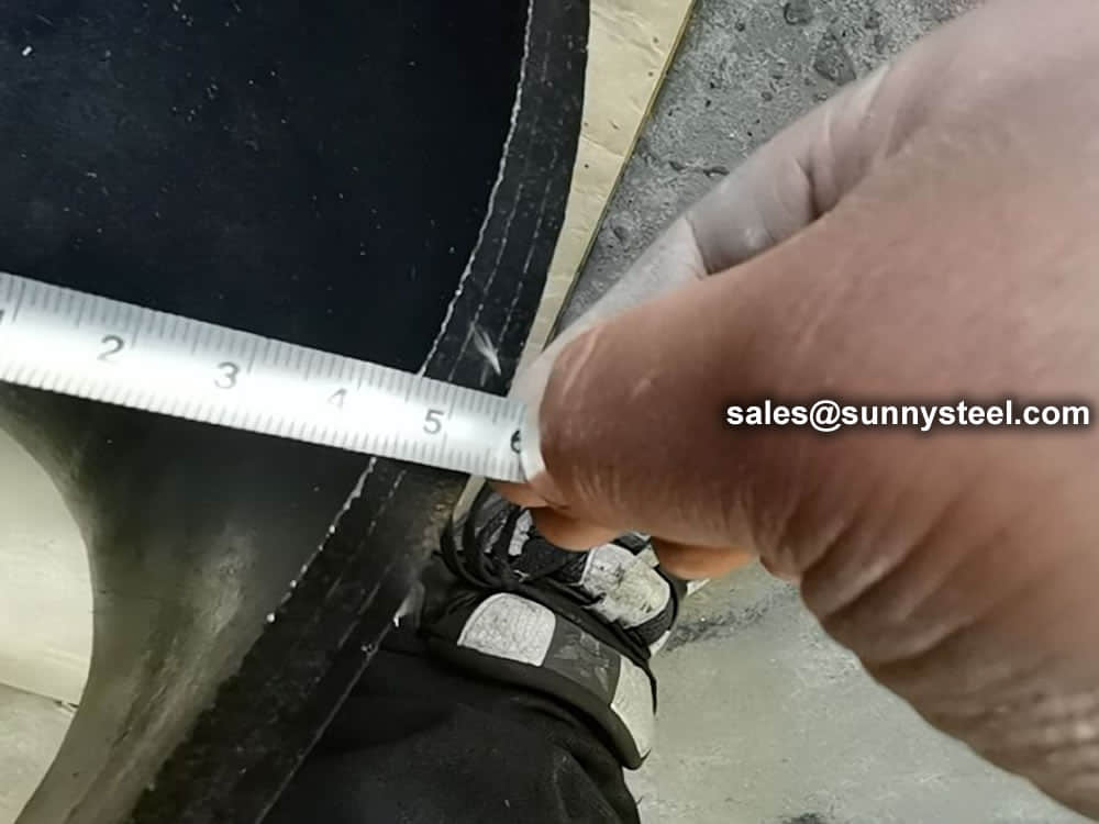
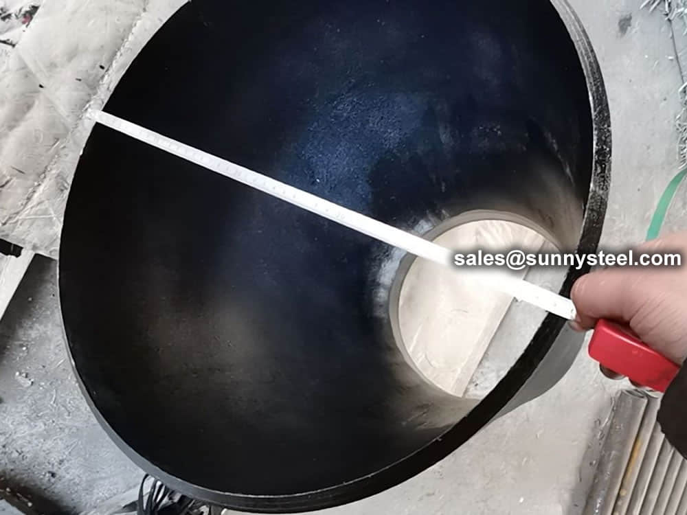
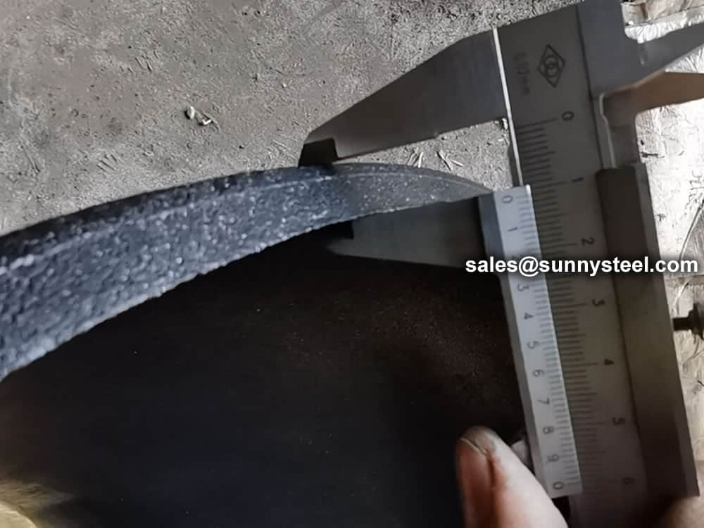
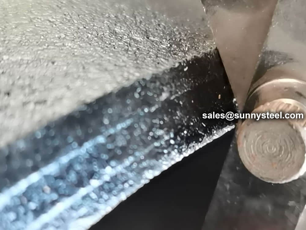
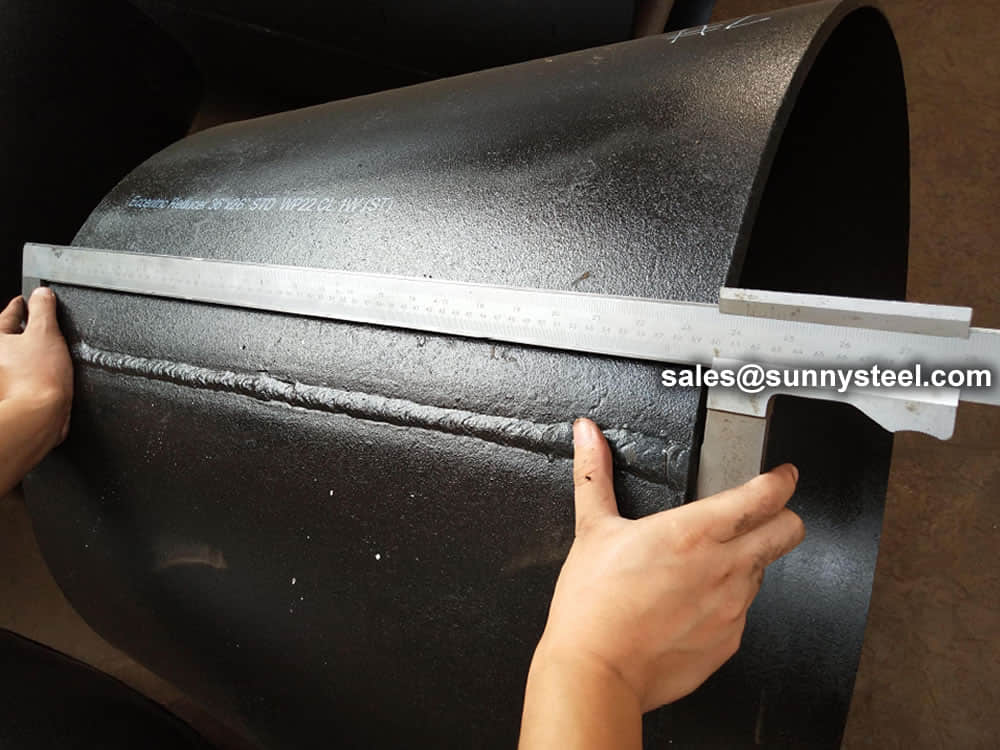
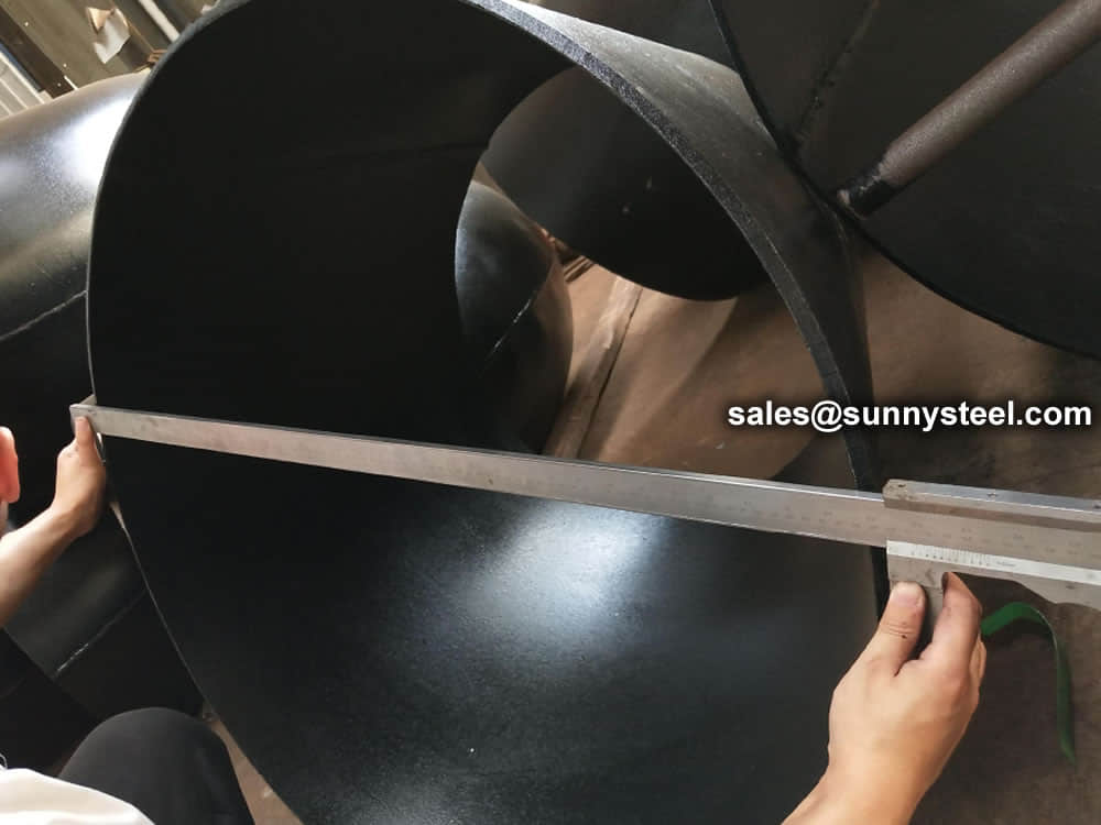
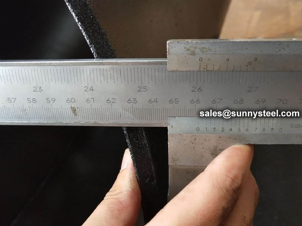
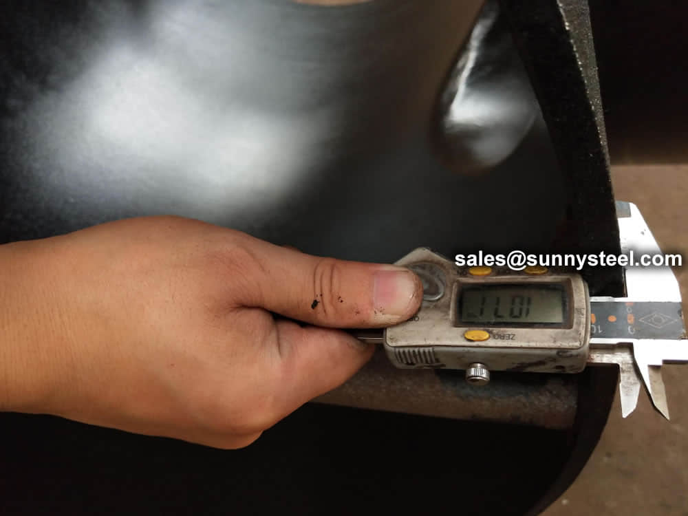
Visual Inspection is conducted on fittings to check any surface imperfections. Both fittings body and weld are checked for any visible surface imperfections such as dents, die marks, porosity, undercuts, etc. Acceptance as per applicable standard.
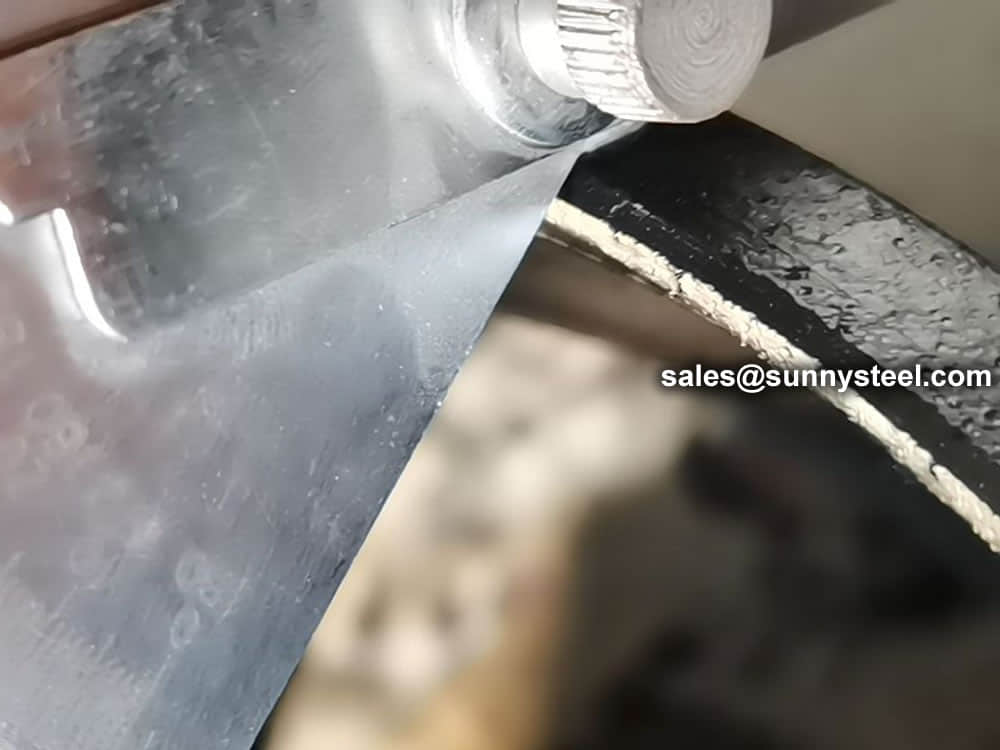
For packing of carbon steel flanges with painting,we would use the bubble wrap to protect the painting.For flanges without painting or oiled with long-term shipment,we would suggest client to use the anti-tarnish paper and plastic bag to prevent the rust.

When you partner with Sunny Steel, you can stop worrying about meeting deadlines thanks to our responsive and timely service. You'll also say goodbye to unnecessary shopping around. Instead, you'll get white glove service from an expert who understands your needs and can get you the materials you need quickly.
