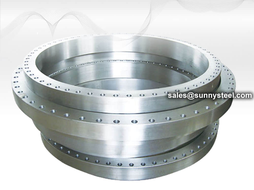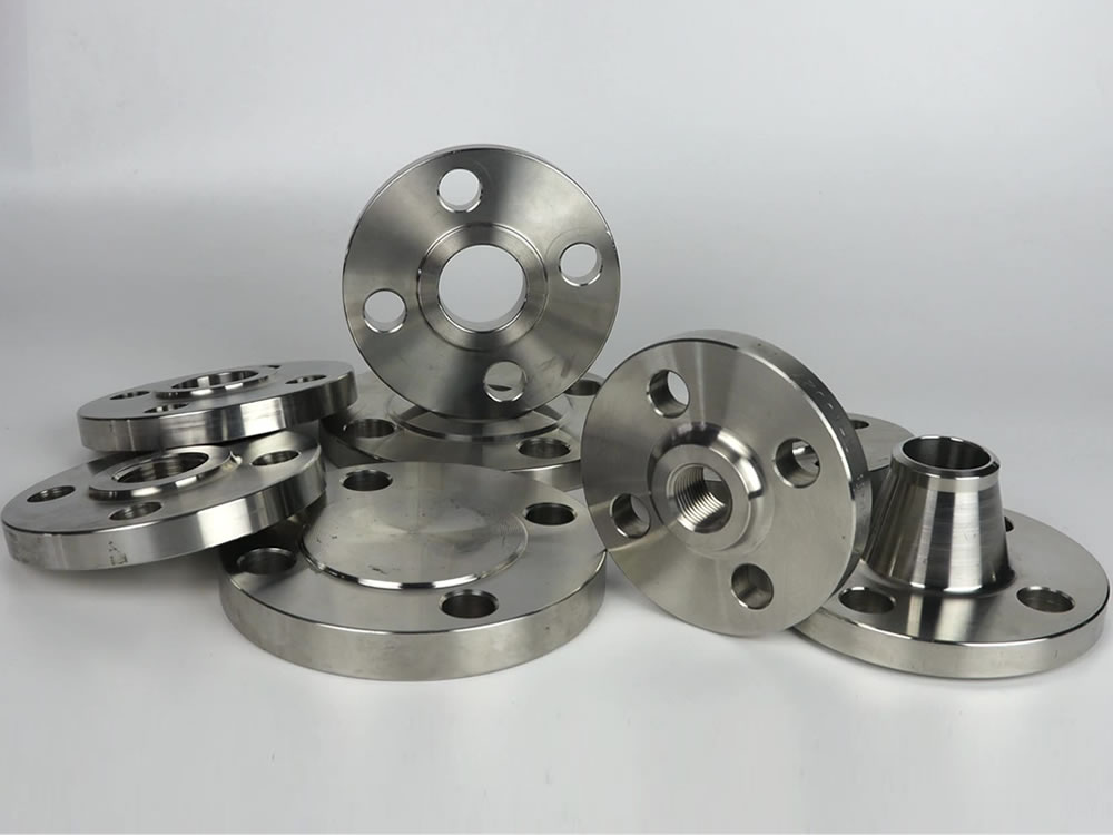
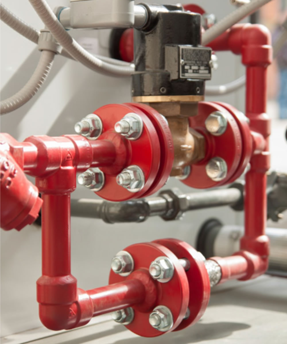
Blind Flanges
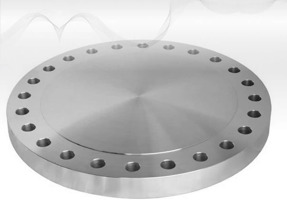
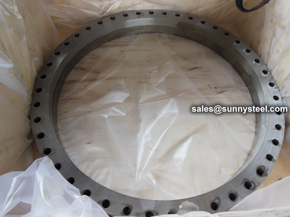
A blind flange (also called a 'closure plate flange') is installed at the end of a piping system to terminate a pipe.
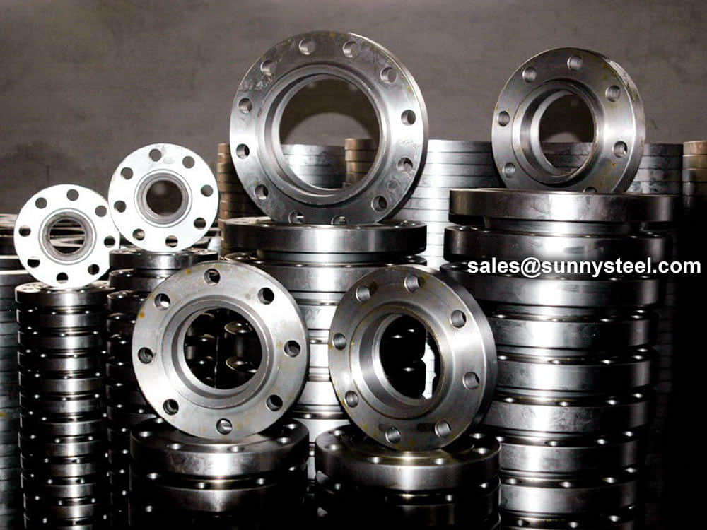
Pipe flanges are basically plates or rings used to connect pipes, valves and other piping equipment to form a piping system.
Download PDFGeneral Flange is a domestic manufacturer of flanges with precision machining capabilities.
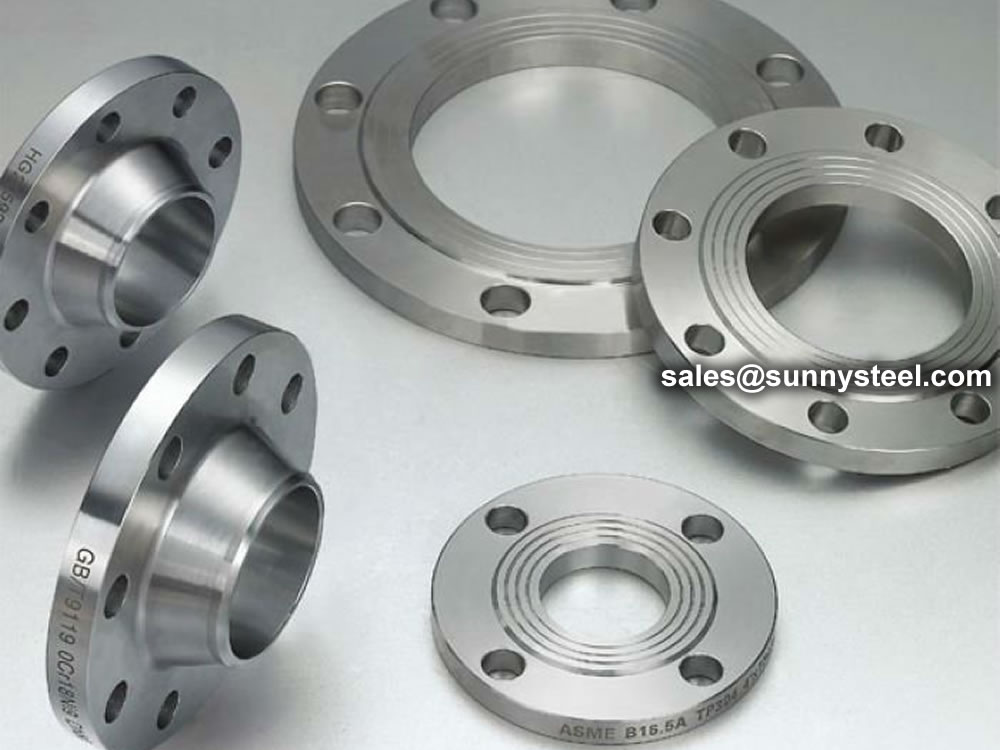
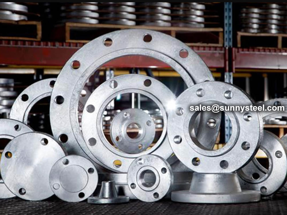
A pipe flange connects piping and components in a piping system by use of bolted connections and gaskets. Most commonly used flanges are weld neck flange, slip on flange, blind flange, socket weld flange, threaded flange and lap joint flange (RTJ Flange). This type of connection in a pipe flange allows for ease of disassembly and separation for repair and regular maintenance. Most common specification for carbon steel and stainless steel flange is ANSI B16.5 / ASME B16.5.
Metal flanges are commonly used for industrial, commercial, and institutional application. Steel pipe flanges are available in variety of styles and pressure classes. Metal flanges are classified from 150 to 2500 # rating. In addition to specifying pressure class, certain flanges such as weld neck flange & socket weld flange also require specifying the pipe schedule. This ensures the pipe bore will match the bore of the weld neck or socket weld flange.
SunnySteel offers wide variety of pipe flanges in carbon steel, stainless steel and nickel alloy. We can also provide special flanges such as long weld neck flange, special material request and high-yield pipe flanges.
There are six most commonly used flanges, also knows as ANSI Flange, ASME B16.5 Flange. However, these designs can be modified to meet the specific functions and requirements of the applications. Therefore, it’s essential to understand the pressure at the flagged joint, the required strength, and the size of pipes involved. With the correct information comes six types of flanges that an individual can choose from. These include:
| Types | Description |
|---|---|
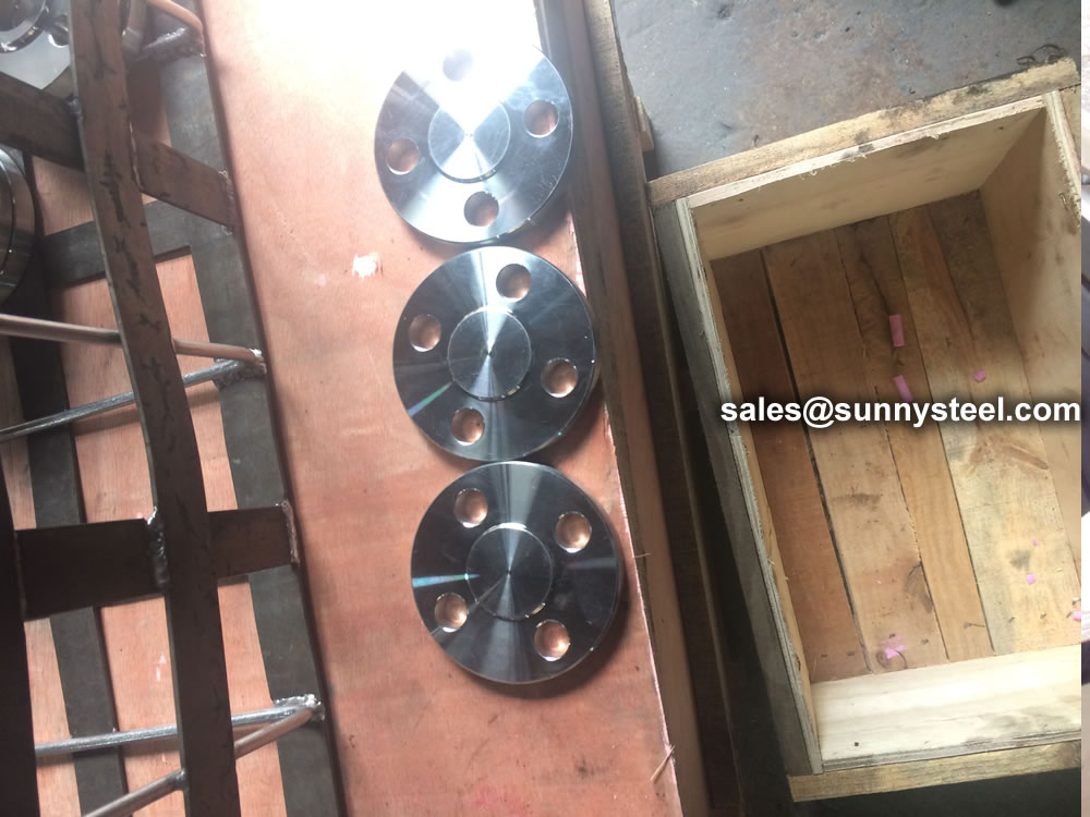
Blind Flange |
These flanges do not have a bore. It is used to blind off a flange or even a valve. When used at the end of a pipe or fitting, it provides an easy to open access for further extension of the pipe. The blind flange and its bolts are stressed more than any other flange. |
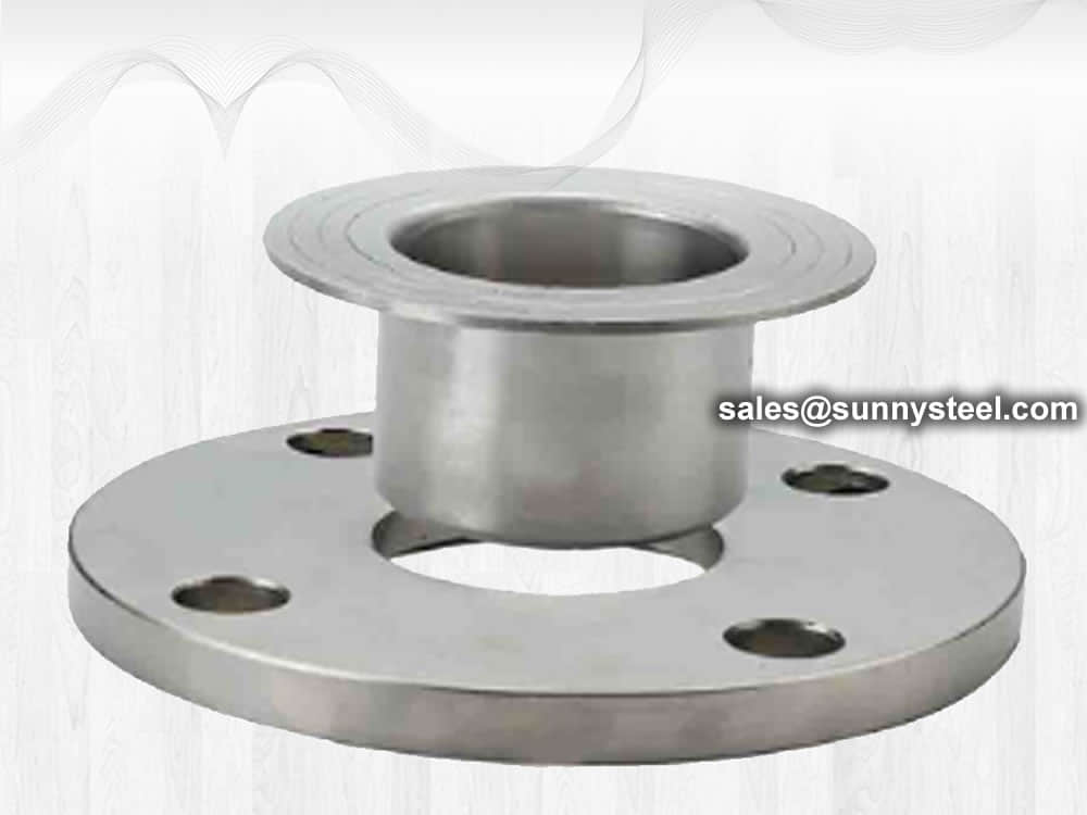
Lap Joint Flange |
This flange is used with a lap joint stub end fitting. It is similar to a slip-on flange, but with two differences. The radius and the flat face, both allow the flange to secure against the stub end fitting. This is useful where alignment of bolt holes is difficult, such as with spools to be attached to flanged nozzles of vessels. A lap joint is used in low pressure applications and not suitable where high external of heavy loads are present. |
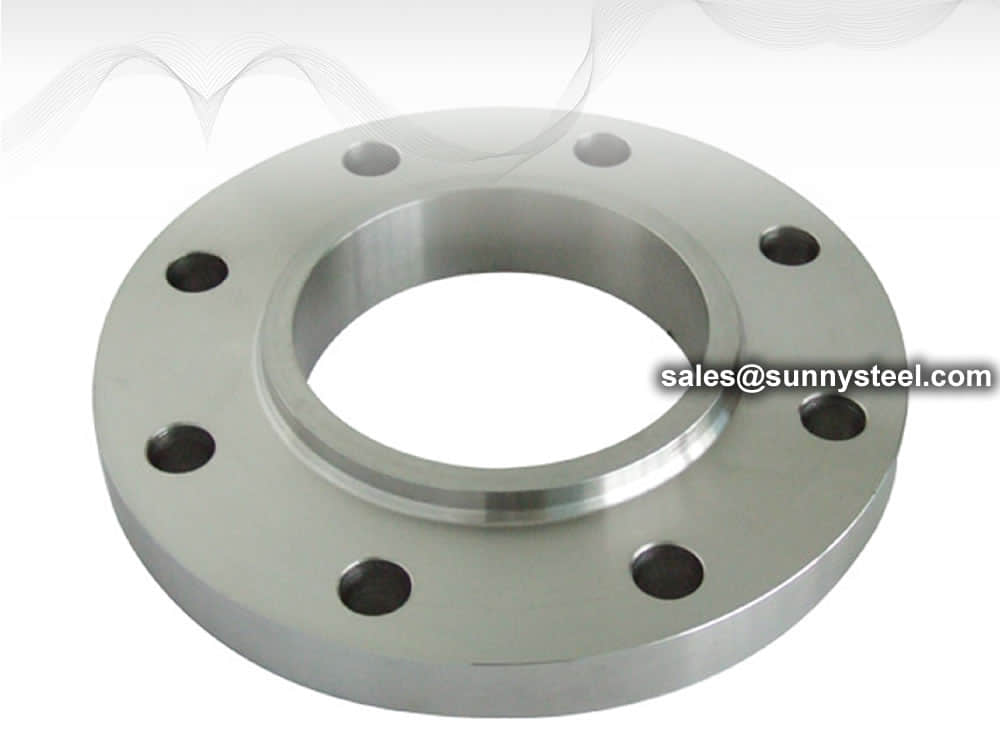
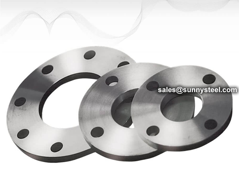
Slip-on Flange |
A slip on flange is designed to slip over the end of pipe. It allows for easy positioning before welding. Both the inside and outside of the pipe is welded on the slip on flange. See picture on the right. The pipe is generally inserted all the way, inside the slip on flange, leaving only the gap equivalent to wall thickness of pipe. These flanges are also knows as ANSI Flange or ASME B16.5 Flange |
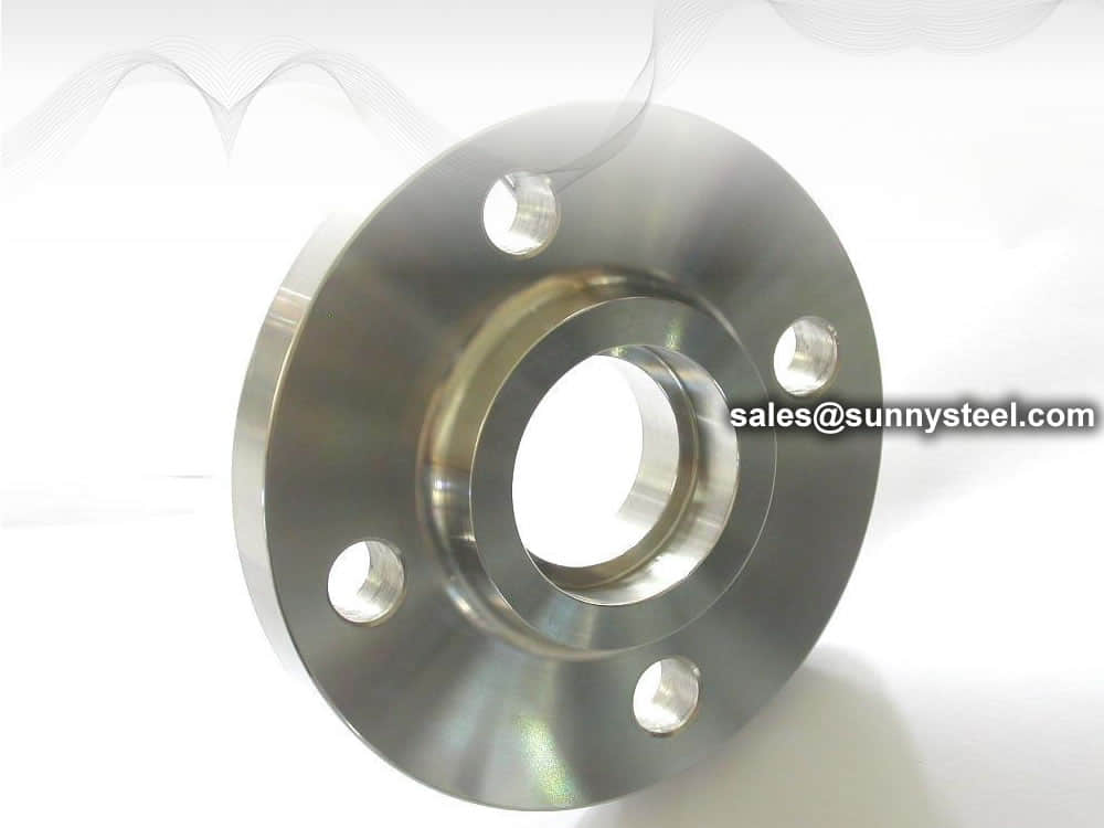
Socket Weld Flange |
This is similar to a slip-on flange, except they have a bored and counter bore. The counter bore allows the pipe to fit into the socket/counter bore. The bore of the flange is the same diameter as the inside of the pipe. These flanges were first designed for small diameter, high pressure pipe. |
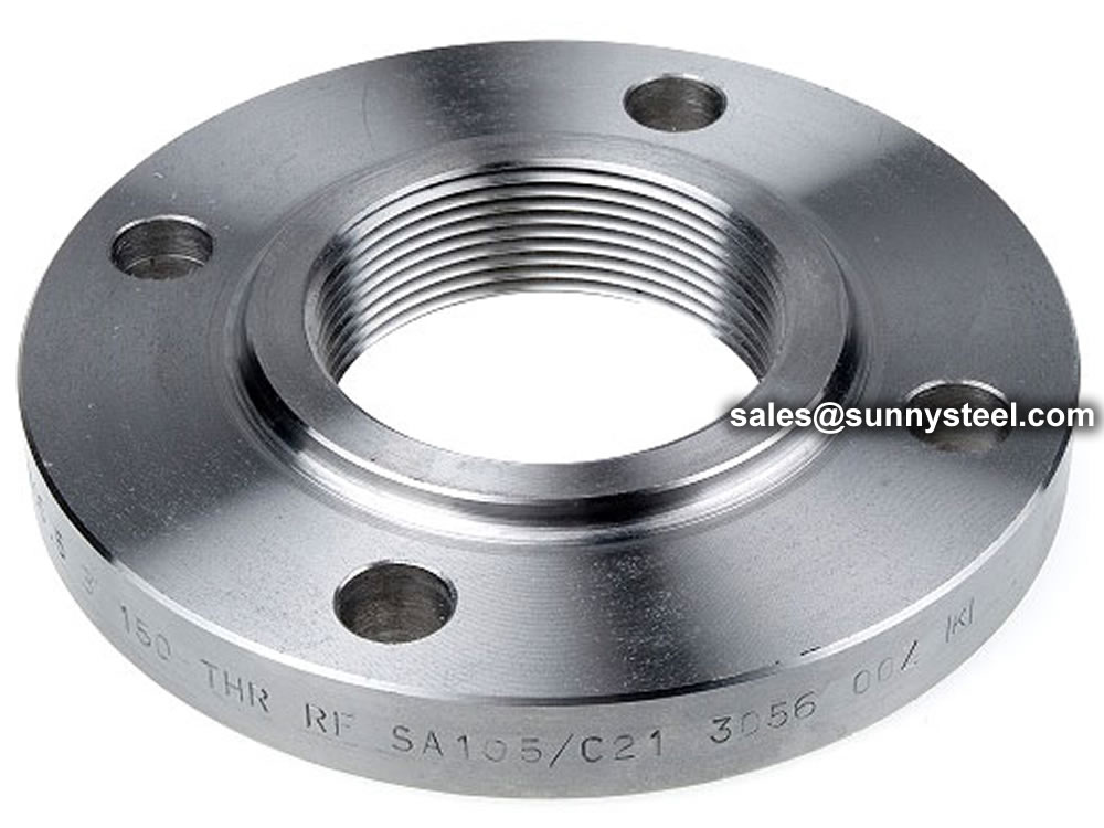
Threaded Flange |
It is similar to a slip-on Flange, but has internal threads. It is normally used for low pressure and not used where temperature or stress is very high. Threaded flange is also called screwed flange or screwed-on flange. This type of flange is used where welding is not an option. Threaded flange is most commonly used on low pressure applications and smaller pipes (up to 4" nominal). |
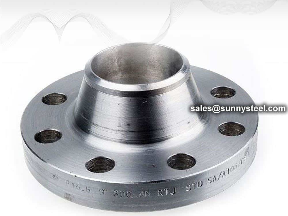
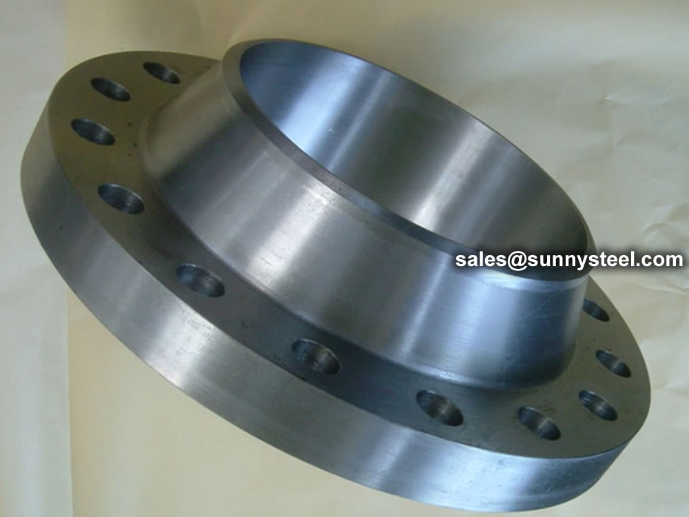
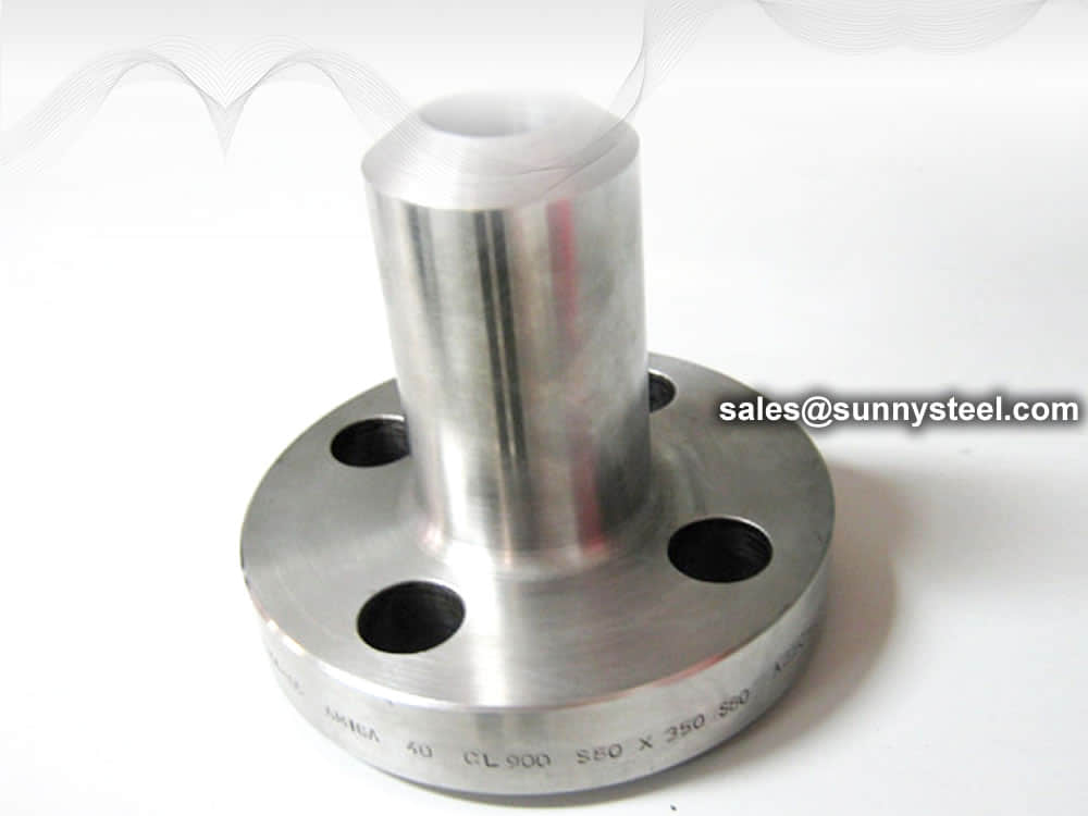
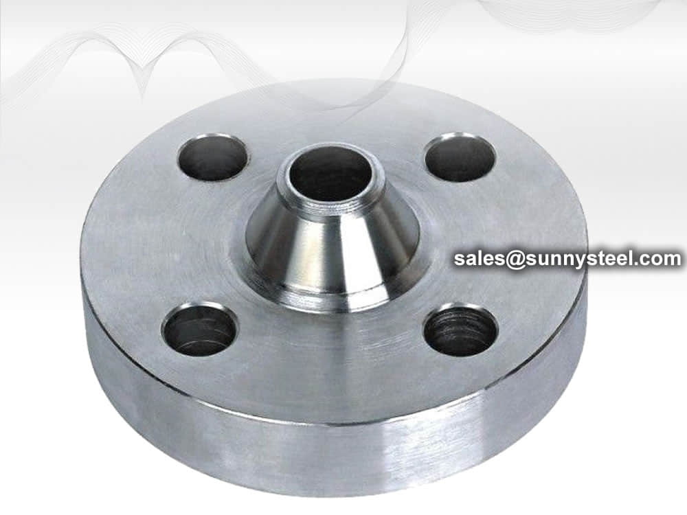
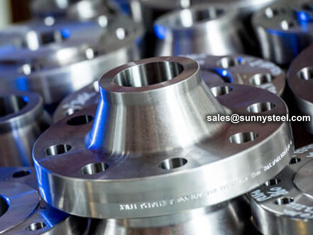
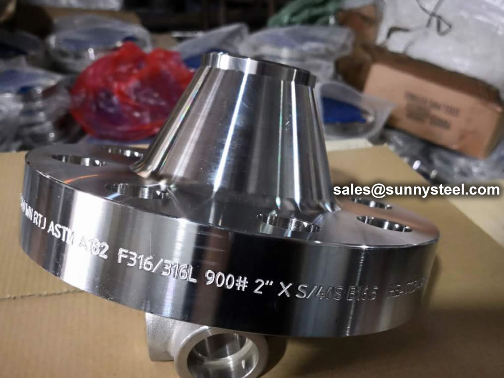
Weld Neck Flange |
This flange type is designed to be connected by a butt weld connection to the pipe or equipment requiring a flanged joint. Welding neck provides good service under variety of temperature and pressure applications. A weld neck flange must specifiy the pipe schedule for the bore. Due to the welding neck, it is a popular choice on pressure vessels and for creating man-holes etc. These flanges are also knows as ANSI Flange or ASME B16.5 Flange |
Pipe flanges are manufactured in all the different materials like stainless steel, cast iron, aluminium, brass, bronze, plastic etc. but the most used material is forged carbon steel and have machined surfaces.
In addition, flanges, like fittings and pipes, for specific purposes sometimes internally equipped with layers of materials of a completely different quality as the flanges themselves, which are "lined flanges".
The material of a flange, is basically set during the choice of the pipe, in most cases, a flange is of the same material as the pipe.
All flanges, discussed on this website fall under the ASME en ASTM standards, unless otherwise indicated. ASME B16.5 describes dimensions, dimensional tolerances etc. and ASTM the different material qualities.
Additionally, the flanges can be modified to form other types, depending on application and functions. These unique designs are made to incorporate specific needs and applications, like reducing flanges to answer to size and orifice flanges to incorporate orifice mounting.
| Types | Description |
|---|---|
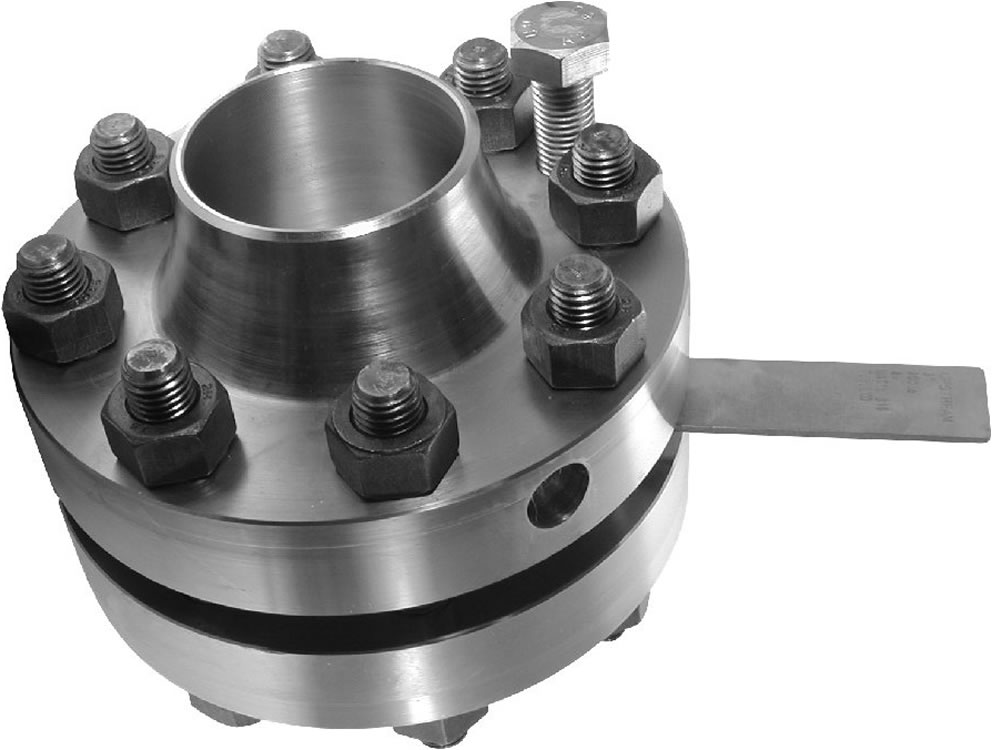
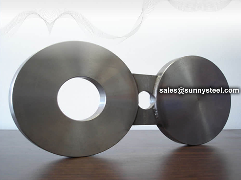
Spectacle blind flange |
A spectacle flange is a specialty flange made of two metal discs attached in the middle by a small section of steel. Spectable flanges get their name because they look like a pair of reading glasses, or spectacles. Spectacle and line blind flanges are similar to a blind flange but different because they fit between two flnges. Spectacle blind gets their name from similarity to pair or eye glasses. Once side of spectacle blind is fully closed for complete flow shutt off, whereas the other end is open for full flow. In this setup the blinds can be rotated without having to take the system apart. It also gives visual confirmation if the line is open or close. |
Reducing Flange |
Reducing flanges are designed for when there is a change in the pipe size. A reducing flange changes the line size without adding an extra fitting. The reduction in a reducing flange is always abrupt compared to a reduction that can be achieved by concentric butt weld reducer. A reducing flange is commonly available as threaded reducing flange or slip on reducing flange. A 6" by 4" reducing slip on flange will have the flange dimension (outer diameter, bolt circle diameter) of an 6" flange but the hole of a 4" flange. This allows it to mate to an 6" pipe via flanged connection but connect a 4" pipe instead. |
Orifice Flange |
Orifice flanges are for metering the volumetric flow rate of liquids and gasses through a pipe. This flange is normally available in weld neck, slip-on, and threaded flanges. Orifice flange is a special flange and is always used in pairs. It is used in conjunction with orifice plate for measure flow of liquids and gases in a piping system. Orifice flanges are pre-drilled with tapped holes made in the flange rims to accommodate metering pipe. The flange that makes up the orifice flange is usually a welding neck flange. Slip on and threaded flange are also used sometimes as end connection. In an orifice flange, the pipe must be drilled to accommodate the tapped hole through which the pressure is sensed. The picture above illustrates the working of orifice flange in a welding neck flange arrangement. |
Weldoflange / Nipoflange |
A weldoflange is an olet connection, it is simular to a nipoflange, both are used for a branch connection on a pipe. |
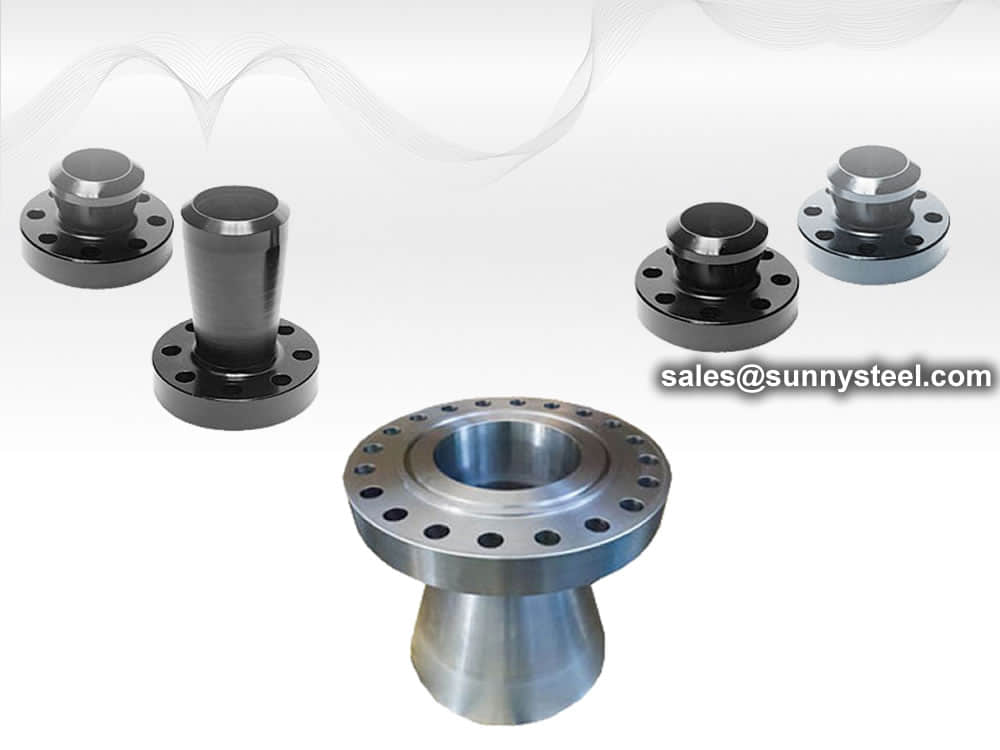
Expander Flange |
An expander flange is similar to a weld neck flange but with the hub expanding to a larger size (one or two sizes). |
Custom flanges |
Our experts are exceptional at machining custom flanges for life. We have experience helping engineers, estimators, purchasing agents and more with their custom flanges. |
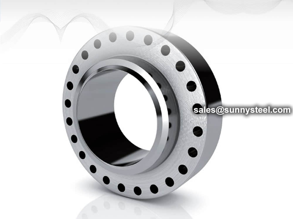
Anchor flange |
An anchor flange is a device to restrain pipe movement in a piping system,it looks like a weld neck flange but has two hubs on the both sides to weld with the pipes,but there is no bolt bores on the anchor flanges. |
| Standard Connection Flange | This flange is normally used for nozzles on pressure vessels and rarely used with pipe. |

Flange face provides a mean to mate the flange with sealing element, usually a gasket. Even though there are many face types, most common flange face types are following;
There are two type of flange face finishes for Raised Face and Flat Face Flanges;
Both serrated finishes have grooves 1/16" deep with 24 to 60 groves per inch.
The back end of raised face flange has a lip that is 1/16" high for pressure classes 150#, 300# and 600#. For flange 900# or higher, the lip is 1/4" thick. Picture above shows a raised face flange.
The back end of a flat face flange, is flat. People sometime confuse it with lap joint flange, however the flat face flange does not have round edges on the bore. Picture above is an example of a flat face flange. compared it to picture from raised flange flange to observe the difference. Flat face is commonly used on cast iron flanges and as mating flanges to pumps and valves in low pressure application.
A ring joint face design has a grooved slot in which a metal ring gasket is inserted to creating a seal with mating flange. The metal ring is available in oval or octagonal shape. Most common material for ring joint gasket is 316 stainless steel which makes it ideal for corrosive applications. The picture above illustrates the ring type gaskets and the ring joint grove finish on the flange.
Lap joint face is used on lap joint flange. It looks similar to flat face flange but has a groove in the bore for mating stub end.
Tongue and groove face has a small contact area for the sealing element providing good gasket compression under low bolt loading. The groove slot acts like an oring groove and provide a good containment means for the gasket. This is ideal under high pressure application. The picture above illustrates the tongue and groove face flange.
Flanges and their joints – Circular flanges for pipes, valves, fittings and accessories, PN designated – Part 1: Steel flanges
This European standard specifies requirements for circular steel flanges in PN designations PN 2,5 to PN 400 and nominal sizes from DN 10 to DN 4000. This standard specifies the flange types and their facings, dimensions, tolerances, threading, bolt sizes, flange face surface finish, marking, materials, pressure/ temperature ratings and flange masses.
Flange faces have to be smooth enough to ensure a tight, leak-free seal for bolted flanges.
| Type A: flat face | Type D: groove face | Type G: O Ring recess |
| Type B: raised face | Type E: spigot | Type H: O Ring groove |
| Type C: tongue face | Type F: recess |

Flanges provide the necessary connections to link pipelines. Faces are the mating surface of a flange.
Different types of flange faces are used as the contact surfaces to seat the sealing gasket material.
| The type of flange | The type of sealing face | Pressure Class(PN,MPA) |
|---|---|---|
| Plate flange(PL) | Raise Face(RF) | 0.25-2.5 |
| Flat Face( FF) | 0.25-1.6 | |
| Slip on flange(SO) | Raise Face(RF) | 0.6-4.0 |
| Flat Face( FF) | 0.6-1.6 | |
| male and female face (MFM) | 1.0-4.0 | |
| Tongue and groove face (TG) | 1.0-4.0 | |
| Welding Neck Flange(WN) | Raise Face(RF) | 1.0-25.0 |
| male and female face (MFM) | 1.0-16.0 | |
| Tongue and groove face (TG) | 1.0-16.0 | |
| Ring Joint Face(RTJ) | 6.3-25.0 | |
| Flat Face( FF) | 1.0-1.6 | |
| Integral type flange(IF) | Raise Face(RF) | 0.6-25.0 |
| male and female face (MFM) | 1.0-16.0 | |
| Tongue and groove face (TG) | 1.0-16.0 | |
| Ring Joint Face(RTJ) | 6.3-25.0 | |
| Flat Face( FF) | 0.6-1.6 | |
| Socket Weld Flange(SW) | Raise Face(RF) | 1.0-10.0 |
| male and female face (MFM) | 1.0-10.0 | |
| Tongue and groove face (TG) | 1.0-10.0 | |
| Thread Flange(Th) | Raise Face(RF) | 0.6-4.0 |
| Flat Face( FF) | 0.6-1.6 | |
| Lap joint Flange(LP) | Raise Face(RF) | 0.6-1.6 |
| male and female face (MFM) | 1.0-1.6 | |
| Tongue and groove face (TG) | 1.0-1.6 | |
| Blind flange(BL) | Raise Face(RF) | 0.25-25.0 |
| male and female face (MFM) | 1.0-16.0 | |
| Tongue and groove face (TG) | 1.0-16.0 | |
| Ring Joint Face(RTJ) | 6.3-25.0 | |
| Flat Face( FF) | 0.25-1.6 |
Other flange facings covered by these standards include the large and small tongue-and-groove facings, and the ring joint facing specifically for ring joint type metal gaskets.
A bolted flange connection is a complex combination of many factors (Flange, Bolts, Gaskets, Process, Temperature, Pressure, Medium). All these various elements are interrelated and depend upon one another to achieve a successful result.
The reliability of the flanged joint depends critically upon competent control of the joint making process.
Remember the types of flanges described in the beginning of this article? (Welding Neck, Slip-On, Threaded, Socket Weld, Lap-Joint and Blind), well those were the standard types, now you’ll see that the types of flanges available in the type of the flange is very similar to them, so all the “pros” and “cons” described there can be applied here.
The types divided the flanges in three groups: loose, integral and optional. Below I’ll describe these types according to the Code.
This type covers those designs in which the flange has no direct connection to the nozzle neck, vessel, or pipe wall, and designs where the method of attachment is not considered to give the mechanical strength equivalent of integral attachment.
This type covers designs where the flange is cast or forged integrally with the nozzle neck, vessel or pipe wall, butt welded thereto, or attached by other forms of arc or gas welding of such a nature that the flange and nozzle neck, vessel or pipe wall is considered to be the equivalent of an integral structure. In welded construction, the nozzle neck, vessel, or pipe wall is considered to act as a hub.
This type covers designs where the attachment of the flange to the nozzle neck, vessel or pipe wall is such that the assembly is considered to act as a unit, which shall be calculated as an integral flange, except that for simplicity the designer may calculate the construction as a loose type flange provided none of the following values is exceeded: g0 = 5/8″ (16 mm), B/g0 = 300, P = 300 psi (2 MPa) and operating temperature = 700°F (370°C).

Pipe flanges are manufactured in all the different materials like stainless steel, cast iron, aluminium, brass, bronze, plastic etc. but the most used material is forged carbon steel and have machined surfaces.
Flanges are welded to pipe and equipment nozzle. Accordingly, it is manufactured from the following materials;
The list of materials used in manufacturing is covered in ASME B16.5 & B16.47.
Commonly used Forged material grads are
| Material | Fittings | Flanges | Valves | Bolts & Nuts |
|---|---|---|---|---|
| Carbon Steel | A234 Gr WPA | A105 | A216 Gr WCB | A193 Gr B7 A194 Gr 2H |
| A234 Gr WPB | A105 | A216 Gr WCB | ||
| A234 Gr WPC | A105 | A216 Gr WCB | ||
| Carbon Steel Alloy High-Temp |
A234 Gr WP1 | A182 Gr F1 | A217 Gr WC1 | A193 Gr B7 A194 Gr 2H |
| A234 Gr WP11 | A182 Gr F11 | A217 Gr WC6 | ||
| A234 Gr WP12 | A182 Gr F12 | A217 Gr WC6 | ||
| A234 Gr WP22 | A182 Gr F22 | A217 Gr WC9 | ||
| A234 Gr WP5 | A182 Gr F5 | A217 Gr C5 | ||
| A234 Gr WP9 | A182 Gr F9 | A217 Gr C12 | ||
| Carbon Steel Alloy Low-Temp |
A420 Gr WPL6 | A350 Gr LF2 | A352 Gr LCB | A320 Gr L7 A194 Gr 7 |
| A420 Gr WPL3 | A350 Gr LF3 | A352 Gr LC3 | ||
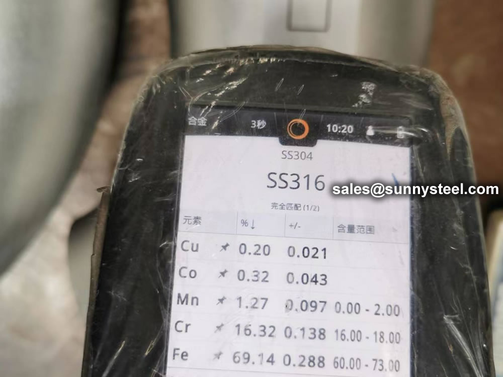
| Austenitic Stainless Steel | A403 Gr WP304 | A182 Gr F304 | A182 Gr F304 | A193 Gr B8 A194 Gr 8 |
| A403 Gr WP316 | A182 Gr F316 | A182 Gr F316 | ||
| A403 Gr WP321 | A182 Gr F321 | A182 Gr F321 | ||
| A403 Gr WP347 | A182 Gr F347 | A182 Gr F347 |
ASTM standards define the specific manufacturing process of the material and determine the exact chemical composition of pipes, fittings and flanges, through percentages of the permitted quantities of carbon, magnesium, nickel, etc., and are indicated by "Grade".
The usual materials of flanges include stainless steel, carbon steel, aluminum and plastic. The choice of the material largely depends on the purpose of the flange. For example, stainless steel is more durable and is necessary for heavy use. On the other hand, plastic is more feasible for use in the home because of its reasonable price and easy installation. The materials used for flanges are under the designation of the American Society of Mechanical Engineers.
The most common materials for pipe flanges (forged grades) are: ASTM A105 (carbon steel high temperature to match A53/A106/API 5L pipes), A350 Grades LF1/2/3 (carbon steel low temperature to match A333 pipes), A694 Grades F42 to F80 (high yield carbon steel to match API 5L pipe grades), ASTM A182 Grades F5 to F91 (alloy steel flanges to match A335 pipes), A182 Grade F304/316 (stainless steel flanges to match A312 SS pipes), A182 Gr. F44/F51/F53/F55 (duplex and super duplex to match A790/A928 pipes) and various nickel alloy grades (Inconel, Incoloy, Hastelloy, Monel).
The material qualities for these flanges are defined in the ASTM standards.
For example, a carbon steel pipe can be identified with Grade A or B, a stainless-steel pipe with Grade TP304 or Grade TP321, a carbon steel fitting with Grade WPB etc.


The most frequently asked questions regarding flanges and flange fittings have to do with how flanges fit on specific steel tube and steel pipe ends.
Flanges have flat or flush surfaces that are vertical to the pipe to which they are attached. The attachment process involves mechanically joining two or more faces using bolts, adhesives, collars, or welds. Due to the attachment requirements, a flange must fit the equipment or pipe that it’s designed. That’s why it’s necessary to check all the possible specifications and dimensions to ascertain that it’s of the right size, type, and material.
Pipe flanges, gaskets, and bolts are the three parts that comprise a flanged connection. Gaskets and bolts are typically made of the same flange materials or a material approved for the pipe components. Each component comes in various materials that suit specific applications and must be matched correctly for proper functioning. The gaskets come in two conventional types: full-face gaskets and ring gaskets. Full-face gaskets have the bolt holes visible and pair up with raised-face gaskets. Ring gaskets tend to be smaller rings minus the bolt holes and pair up with flat-faced flanges. Securing the flange components requires matching the surfaces evenly and plumb, adjusting as needed for a uniform fit. Once all surfaces match, bring the flanges together and secure at least two of the bolts. Refine the alignment, so the remaining bolt holes match and their corresponding bolts are tightly secured.
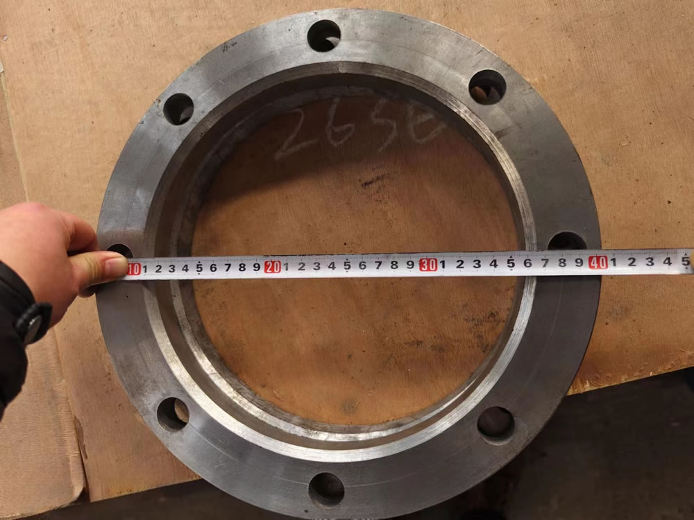
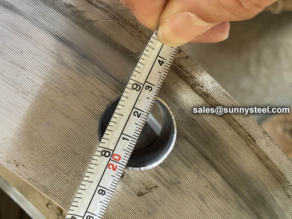
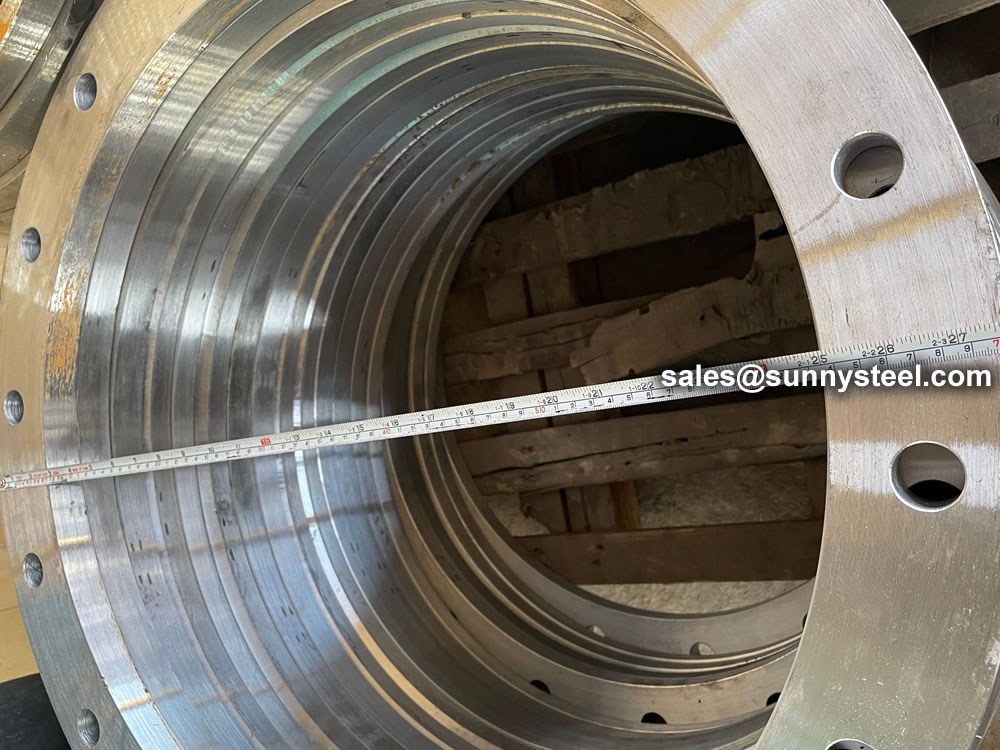
Properly sizing a flange for pipe use depends not only on the type of flange but its compatible piping. The pipe must slip into the flange’s inside diameter easily and securely, and the outside diameter should cover wall holes. Once you determine the specific flange type and material you need for the job, you’ll need to take several measurements. The four measurements you’ll need are the inside diameter, outside diameter, bolt hole count, and bolt hole center. You’ll need to align each of these measurements from opposing bolt holes to get the most accurate readings. Take all measurements from edge to edge and try to get as precise as possible to match the correct product. Round up bolt diameter to the next half or whole step since bolts measure half or whole inches. Once you have all four measurements, check them against the manufacturer’s table to find the correct flange. Most manufacturers list these specifications on their websites for easy reference.
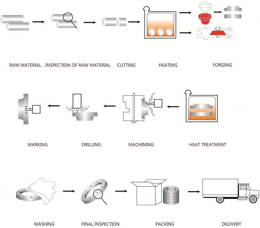
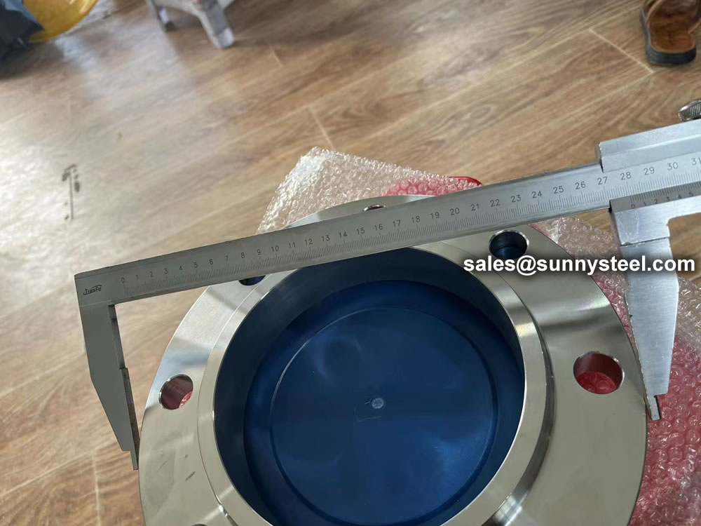
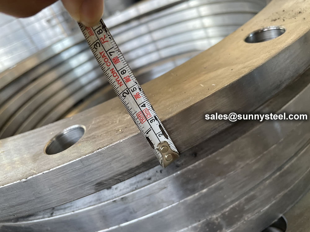
Before dispatching from manufacture each flange is inspected to ensure quality. During an inspection you have to check the following;
ASME B16.5 and B16.47 standards cover permissible tolerances for inspection.
Flanges are used to connect pipes or other equipment components in various industries, and they come in a variety of materials and sizes. Flange material standards are developed by standard-setting organizations and describe the properties and characteristics of different materials that can be used to make flanges. Some examples of commonly used flange material standards include:
The choice of flange material standard will depend on various factors such as the application, the environment, the fluid being transported, and the required performance characteristics. For example, high-pressure applications may require flanges made from materials with high strength and durability, while corrosive environments may require flanges made from materials with good resistance to corrosion.
There are many ways to connect flanges, including threading, welding or bolting. The threaded flange is best for low pressure or smaller pipelines because it can maintain its seal. When your pipeline is larger or high pressure, then the welded flange is preferable. A boiler room is one place where welded blind flanges might be used, due to the high pressure involved.
Flanged joints: flanges, bolts and nuts and gaskets
A flange is a external rib at the end of pipes, valves and other flow devices to assemble them.
Dimensions of the flanges are up to specific Standards : DIN, ANSI, AS, BS, JIS
A flanged connection requires two flanges (the “main” and the “companion”), a set of bolts and nuts (whose number depends on the flange diameter and class) and two sealing gaskets. Flanged connections have to be executed and supervised by trained personnel, as the quality of the joint has a critical impact on the performance of the piping system / pipeline (the standard TSE – TS EN 1591 Part 1-4, “Flanges and their joints”, defines a number of requirements for the execution of proper flanged connections). Whereas all elements of the joint are critical, experience shows most leaks are originated by the improper installation of the sealing elements, i.e. the gaskets.
The typical pipe to flange connections are welded or threaded. Welded flanges are used for pipelines and piping systems with high pressures and temperatures, and with diameters above 2 inches.
Threaded connections are instead used for installations of smaller diameter and not subject to severe mechanical forces such as expansion, vibration, contraction, oscillation (forces that would crack the threaded joint). In all these critical cases, butt weld connections are recommended.


Pipe Flange Standards mainly include three systems in the world, ANSI/ASME flange system(American), DIN flange system(European system), JIS flange system, other system made according to this three systems, like GB flange standard, which mainly made according to ANSI/ASME and DIN flange standard, Duwa Piping supplies those flanges with top quality and soonest delivery time.
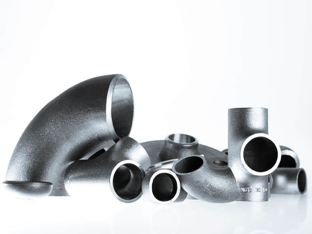
ASTM A234/A234M is a standard specification for piping fittings of wrought carbon steel and alloy steel for moderate and high-temperature service. This specification covers several grades of fittings that are used in various applications in the oil and gas, petrochemical, and power generation industries.
Download PDF| Grade | Type | C | Si | S | P | Mn | Cr | Ni | Mo | Other | ób | ós | δ5 |
|---|---|---|---|---|---|---|---|---|---|---|---|---|---|
| WPB | 0.3 | 0.1min | 0.058 | 0.05 | 0.29-1.06 | 0.4 | 0.4 | 0.15 | V:0.06;Nb:0.02 | 415-585 | 240 | 22 | 197 |
| WPC | 0.35 | 0.1min | 0.058 | 0.05 | 0.29-1.06 | 0.4 | 0.4 | 0.15 | V:0.06;Nb:0.02 | 485-655 | 275 | 22 | 197 |
| WP1 | 0.28 | 0.1-0.5 | 0.045 | 0.045 | 0.3-0.9 | 0.44-0.65 | 380-550 | 205 | 22 | 197 | |||
| WP12 CL1 | 0.05-0.2 | 0.6 | 0.045 | 0.045 | 0.3-0.8 | 0.8-1.25 | 0.44-0.65 | 415-585 | 220 | 22 | 197 | ||
| WP12 CL2 | 0.05-0.2 | 0.6 | 0.045 | 0.045 | 0.3-0.8 | 0.8-1.25 | 0.44-0.65 | 485-655 | 275 | 22 | 197 | ||
| WP11 CL1 | 0.05-0.15 | 0.5-1 | 0.03 | 0.03 | 0.3-0.6 | 1-1.5 | 0.44-0.65 | 415-585 | 205 | 22 | 197 | ||
| WP11 CL2 | 0.05-0.2 | 0.5-1 | 0.04 | 0.04 | 0.3-0.8 | 1-1.5 | 0.44-0.65 | 485-655 | 275 | 22 | 197 | ||
| WP11 CL3 | 0.05-0.2 | 0.5-1 | 0.04 | 0.04 | 0.3-0.8 | 1-1.5 | 0.44-0.65 | 520-690 | 310 | 22 | 197 | ||
| WP22 CL1 | 0.05-0.15 | 0.5 | 0.04 | 0.04 | 0.3-0.6 | 1.9-2.6 | 0.87-1.13 | 415-585 | 205 | 22 | 197 | ||
| WP22 CL3 | 0.05-0.15 | 0.5 | 0.04 | 0.04 | 0.3-0.6 | 1.9-2.6 | 0.87-1.13 | 520-690 | 310 | 22 | 197 | ||
| WP5 CL1 | 0.15 | 0.5 | 0.03 | 0.04 | 0.3-0.6 | 4-6 | 0.44-0.65 | 415-585 | 205 | 22 | 217 | ||
| WP5 CL3 | 0.15 | 0.5 | 0.03 | 0.04 | 0.3-0.6 | 4-6 | 0.44-0.65 | 520-690 | 310 | 22 | 217 | ||
| WP9 CL1 | 0.15 | 1 | 0.03 | 0.03 | 0.3-0.6 | 8-10 | 0.9-1.1 | 415-585 | 205 | 22 | 217 | ||
| WP9 CL3 | 0.15 | 1 | 0.03 | 0.03 | 0.3-0.6 | 8-10 | 0.9-1.1 | 520-690 | 310 | 22 | 217 | ||
| WPR | 0.2 | 0.05 | 0.045 | 0.4-1.06 | 1.6-2.24 | 435-605 | 315 | 22/28 | 217 | ||||
| WP91 | 0.08-0.12 | 0.2-0.5 | 0.01 | 0.02 | 0.3-0.6 | 8-9.5 | 0.4 | 0.85-1.05 | See sdandard | 585-760 | 415 | 20 | 248 |
| WP911 | 0.09-0.13 | 0.1-0.5 | 0.01 | 0.02 | 0.3-0.6 | 8.5-10.5 | 0.4 | 0.9-1.1 | See sdandard | 620-840 | 440 | 20 | 248 |
For each reduction of 0.01% below the specified C maximum, an increase of 0.06% Mn above the specified maximum will be permitted, up to a maximum of 1.35%.
The sum of Cu, Ni, Cr, and Mo shall not exceed 1.00%.
The sum of Cr and Mo shall not exceed 0.32%.
The maximum carbon equivalent (C.E.) shall be 0.50, based on heat analysis and the formula C.E.=C+Mn/6+(Cr+Mo+V)/5+(Ni+Cu)/15.
| Tensile Requirements | WPB | WPC, WP11CL2 | WP11CL1 | WP11CL3 |
|---|---|---|---|---|
| Tensile Strength, min, ksi[MPa] (0.2% offset or 0.5% extension-under-load) |
60-85 [415-585] |
70-95 [485-655] |
60-85 [415-585] |
75-100 [520-690] |
| Yield Strength, min, ksi[MPa] | 32 [240] |
40 [275] |
30 [205] |
45 [310] |
A flange is a method of connecting pipes, valves, pumps, and other equipment to form a piping system. It also provides easy access for cleaning, inspection, or modification.
When a piping joint requires to be dismantled, flanges are being used. These are primarily used on equipment, valves, and specialty items. Breakout flanges are provided at predetermined intervals in certain pipelines where maintenance is a regular occurrence. The flanges, gaskets, and bolting make up a flanged joint, which is made up of three separate but interconnected components. To achieve a leak-proof joint, special controls are required in the selection and application of all of these elements.
Here are the details of Flanges about their advantages and their applications.
Pipes, valves, pumps, and other parts are connected with flanges to form a piping system. Generally, flanges are welded or screwed together. The use of flanges makes pipe system maintenance and repair a breeze. Instead of taking the entire pipe for inspection, a small section of the pipe can be carefully investigated to use a flange to locate the fault.
The following are the five most important benefits of The following are the five most important benefits of flanges:
A flange is a method of connecting pipes, valves, pumps, and other equipment to form a piping system. It also provides easy access for cleaning, inspection, or modification. Flanges are usually welded or screwed.
In many applications, engineers need to find a way to close off a chamber or cylinder in a very secure fashion, usually because the substance inside must differ from the substance outside in composition or pressure.
They do this by fastening two pieces of metal or other material together with a circle of bolts on a lip. This “lip” is a flange.
You can connect two sections of metal piping by soldering or welding them together, but pipes connected in this way are very susceptible to bursting at high pressures. A way of connecting two sections of pipe more securely is by having flanged ends that you can connect with bolts. This way, even if gases or liquids build up to high pressures inside the pipe, it will often hold with no problem.
In order to connect two sections of a large, enclosed area, it is often best to used flanges and bolts. An example of this is the connection between the engine and the transmission in an automobile. In this case, both the engine and the transmission contain a number of moving parts that can easily get damaged if they get dust or other small objects inside of them. By connecting the outer casings of the engine and transmission in this way, engineers protect the inner workings of both.
Flanges have a specific purpose in cameras and other electronic devices. Though flanges in such items do not usually have to sustain high pressures, they do have to hold tight so they can keep out harmful particles. These flanges are usually found connecting two different materials, such as the glass of a lens and the rest of the body of the camera.
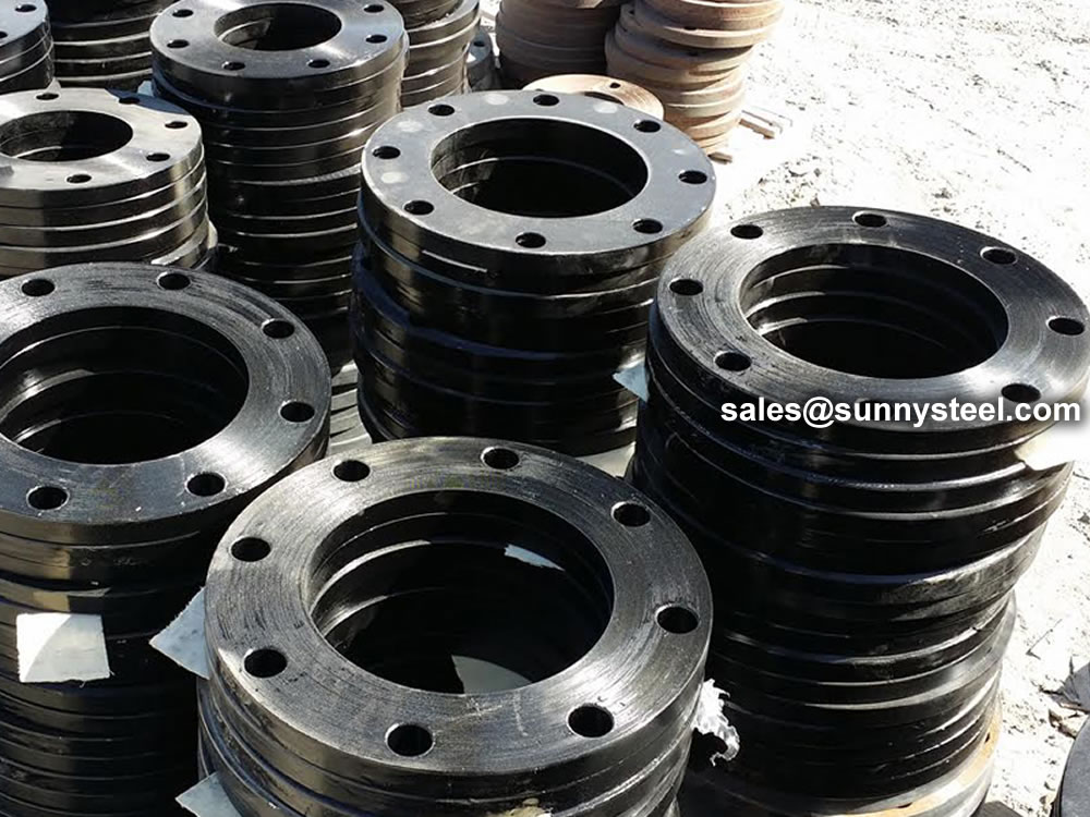
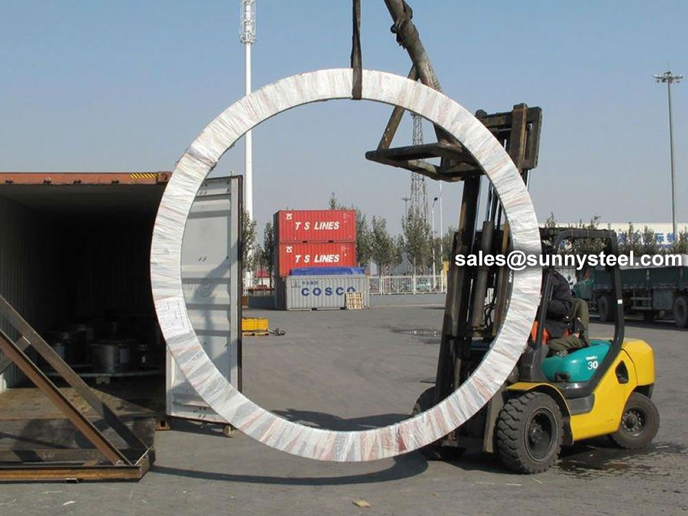
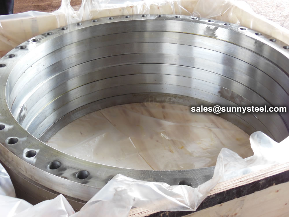
Steel flanges must be packed with seaworthy packing method then delivery to customers, usually the packing way include wooden box, wooden pallet, iron & steel cage, iron & steel pallet etc.
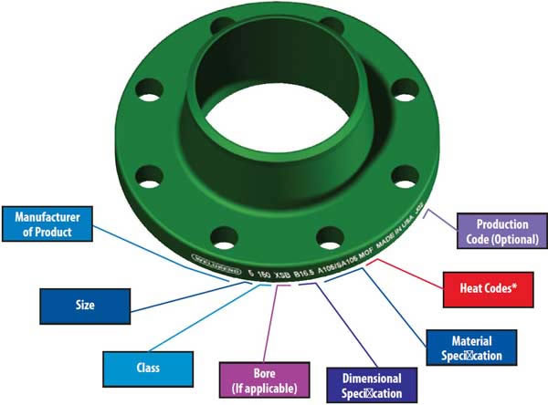
Flange markings are governed by ANSI ASME codes. Flange marking includes;
ASME B16.5 and B16.47 standards cover permissible tolerances for inspection.
Because of the normal wooden boxes or wooden pallets have to do fumigation treatment, we usually use plywood pallet or plywood case or box to pack steel flanges without fumigation treatment.


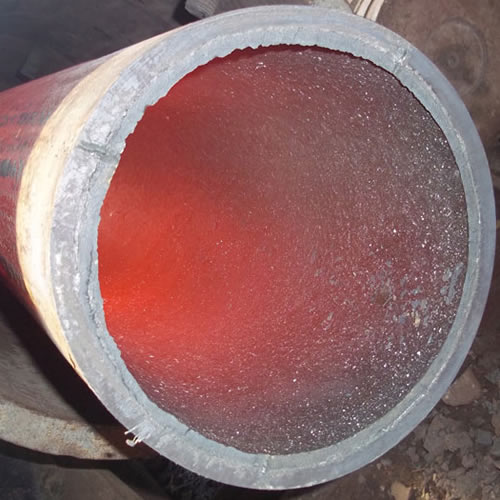
Ceramic lined pipe is made through self-propagating high-temperature synthesis (SHS) technique.
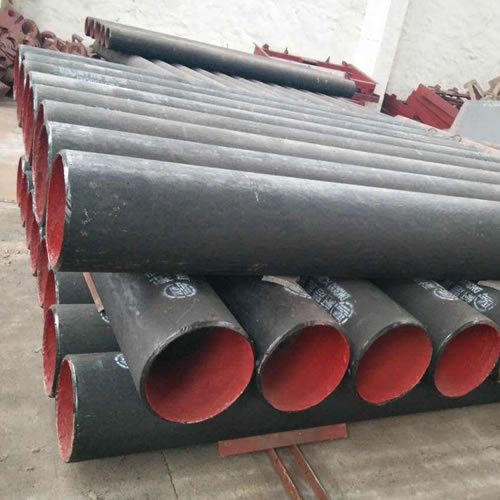
Cast basalt lined steel pipe is composed by lined with cast basalt pipe, outside steel pipe and cement mortar filling between the two layers.
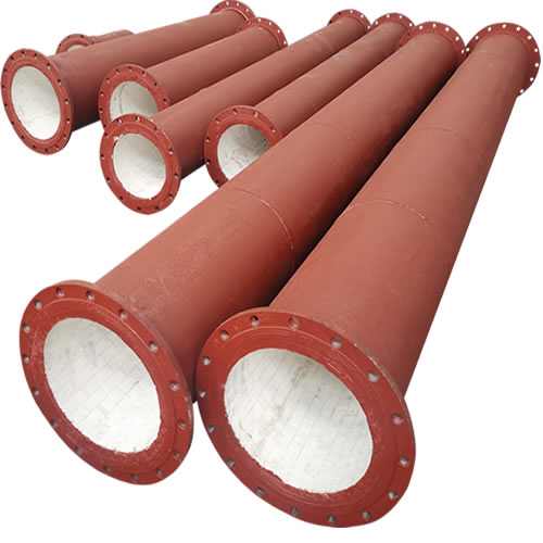
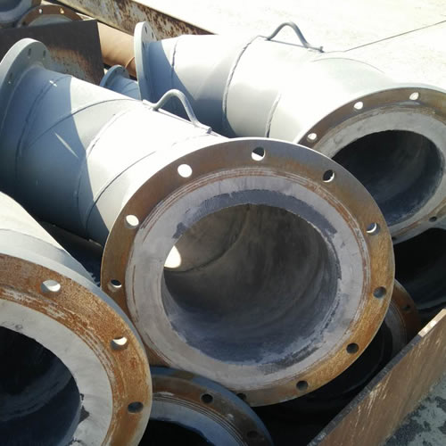
Ceramic tile lined pipes have very uniform coating of specially formulated ceramic material that is affixed to the inner of the pipe.
The material of the rare earth alloy wear-resistant pipe is ZG40CrMnMoNiSiRe, which is also the grade of rare earth alloy steel.
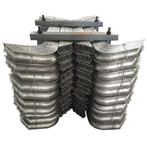
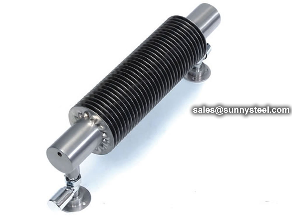
Tubes Erosion Shields are used to protect boiler tubing from the highly erosive effects of high temperatures and pressures thereby greatly extending tube life.
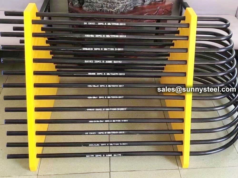
The ASTM A213 T91 seamless tubes are primarily used for boiler, superheater, and heat-exchanger.

When you partner with Sunny Steel, you can stop worrying about meeting deadlines thanks to our responsive and timely service. You'll also say goodbye to unnecessary shopping around. Instead, you'll get white glove service from an expert who understands your needs and can get you the materials you need quickly.