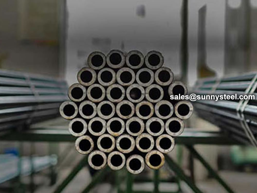
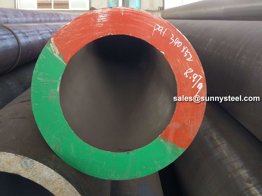
ASTM A335 Chrome Moly Pipe
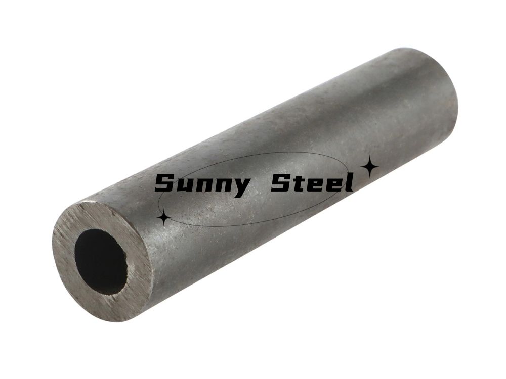
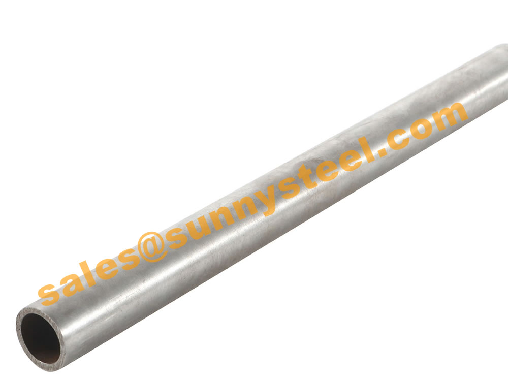
ASTM A335 Pipe (ASME S/A335, Chrome-Moly) is a seamless ferritic Alloy-Steel Pipe for high-temperature service.
EN 10216-1 is a European standard that specifies the technical delivery conditions for two qualities of non-alloy steel tubes.
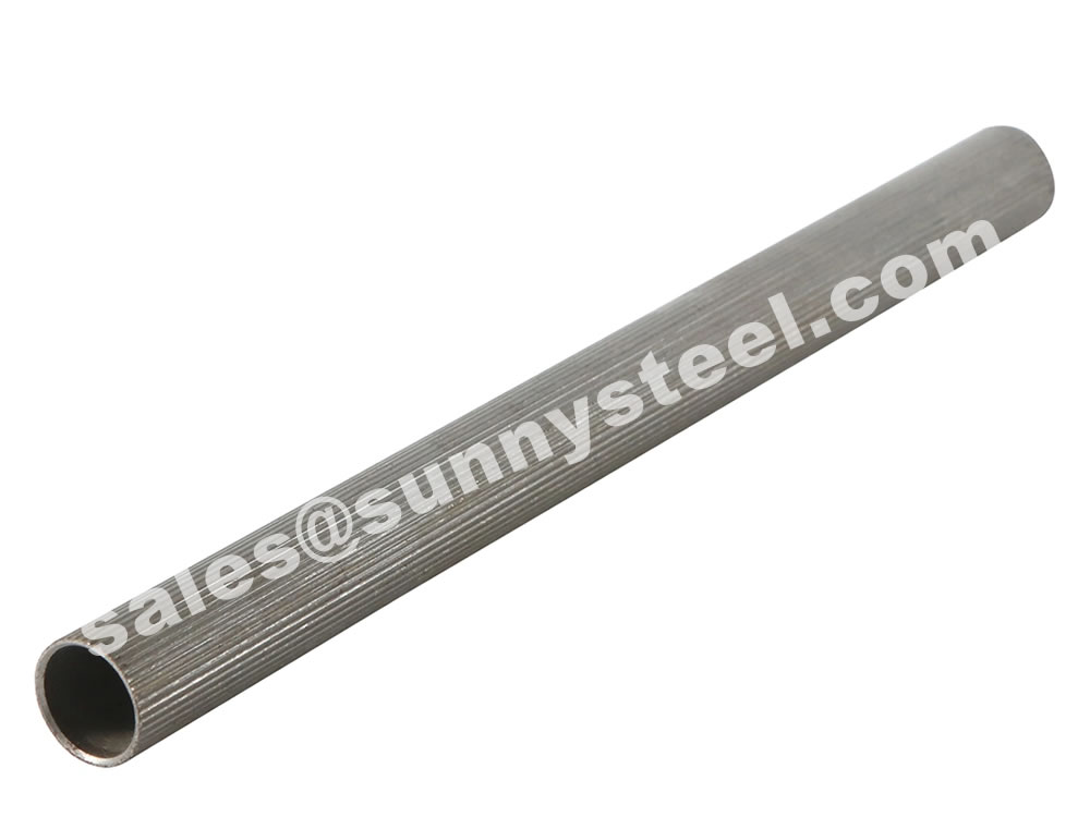
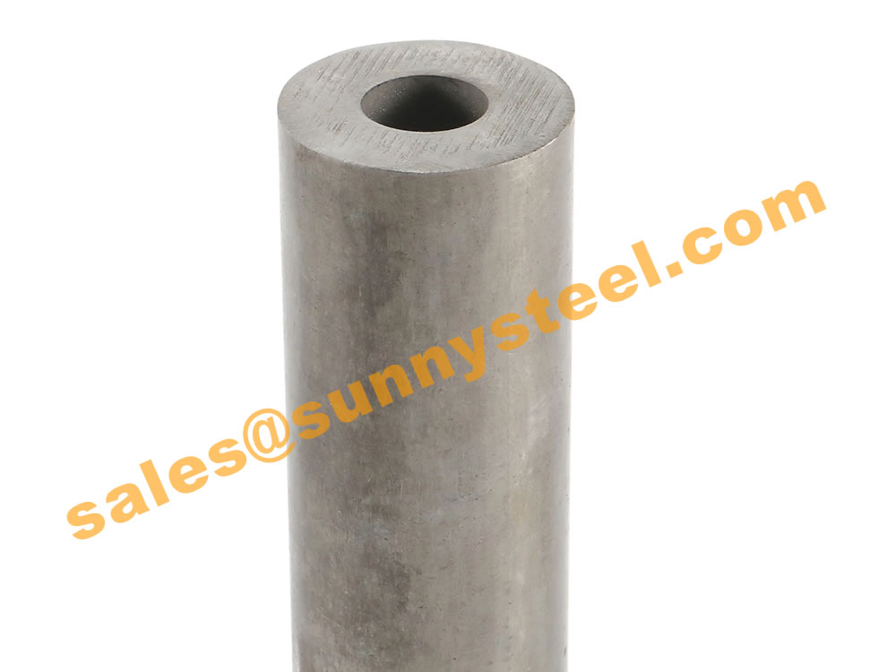
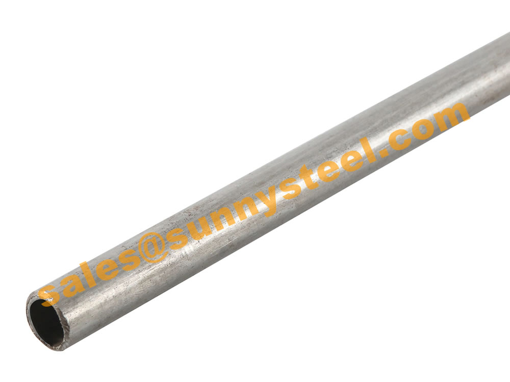
The tubes are seamless and have a circular cross section. They have specified room temperature properties and are suitable for pressure applications.
The two qualities are TR1 and TR2. The tubes are mainly used as boiler water tubes, smoke tubes, superheater tubes, and air preheater tubes.
The EN 10216 standard has five parts, each specifying the delivery conditions for alloy or non-alloy seamless steel tubes.
EN 102161 defines two qualities of seamless tubes: TR1 and TR2.
These tubes are made of nonalloy quality steel.
The steel used in these tubes is fully killed, ensuring uniform properties.
The tubes are varnished on the outside to prevent rusting.
EN 102161 seamless steel tubes are used for various pressure purposes, including in the production of storage tanks made of heatresistant steels used in boilermaking and toolmaking.
The standard includes variants like P195TR1 and P265TR2, each with specified room temperature properties.
These tubes find applications in boiler water tubes, smoke tubes, superheater tubes, air preheater tubes, and more.
Cold Drawn Seamless Mechanical Tubing (CDS) is a type of EN 102161 tube known for its uniform tolerances, enhanced machinability, and increased strength.
Tubes conforming to EN 102161 can be supplied in various lengths, including random lengths.
Different grades of P265GH tubes are used for different applications. For example, the EN 10216-2 P265GH-TC1 grade has increased silicon, manganese, and phosphorus content, which improves its corrosion resistance and wear resistance.
This part of EN1026 specifies the technical delivery conditions in two test categories for seamless tubes for circular cross section, with specified elevated temperature properties, made of non-alloy and alloy steel.
P265GH tubes are primarily used in the manufacture of boilers, pressure vessels, and pipes for transporting hot liquids.
Seamless steel tubes for pressure purposes - Technical delivery conditions -Part 1: Non-alloy steel tubes with specified room temperature properties
Specifies the technical delivery conditions for two qualities, T1 and T2, of seamless tubes of circular cross section, with specified room temperature properties, made of non-alloy quality steel.
Seamless steel tubes for pressure purposes - Technical delivery conditions - Part 2: Non alloy and alloy steel tubes with specified elevated temperature properties; German version EN 10216-2:2002+A2:2007
The document specifies the technical delivery conditions in two test categories for seamless tubes of circular cross section, with specified elevated temperature properties, made of non-alloy and alloy steel.
Seamless steel tubes for pressure purposes -Technical delivery conditions - Part 3: Alloy fine grain steel tubes
Specifies the technical delivery conditions in two categories for seamless tubes of circular cross section, made of weldable alloy fine grain steel
Seamless steel tubes for pressure purposes - Technical delivery conditions -Part 4: Non-alloy and alloy steel tubes with specified low temperature properties
Specifies the technical delivery conditionsin two categories for seamless tubes of circular crossection, made with specified low temperature properties, made of non-alloy and alloy steel.
Seamless steel tubes for pressure purposes - Technical delivery conditions-Part 5: Stainless steel tubes; German version EN 10216-5:2004, Corrigendum to DIN EN 10216-5:2004-11; German version EN 10216-5:2004/AC:2008
This Part of this European Standard specifies the technical delivery conditions in two test categories for seamless tubes of circular cross-section made of austenitic (including creep resisting steels) and austenitic-ferritic stainless steel which are applied for pressure and corrosion resisting purposes at room temperature, at low temperatures or at elevated temperatures. It is important that the purchaser, at the time of enquiry and order, takes in account the requirements of the relevant national legal regulations for the intended application.
Steel is common called carbon steel because of the mixture of carbon atoms with iron atoms. The added elements provide the steel with ductility and strength. During the smelting process, other elements, such as aluminum is added to the steel making it an alloy steel. Non-alloy steel has no elements added to the steel as it is smelted.
The manufacturing of steel is done by placing ore in a furnace a smelting the ore. The smelting process removes any impurities in the iron ore. Once the first smelting process is performed, the steel still has too much carbon content to become non-alloy steel. The smelting process is performed again and again until the carbon content in the ore falls below 1.5 percent of the total content.
The smelting process melts the iron ore. By melting the ore, the extraction of elements and impurities can be accomplished. The manufacturer only wants the iron and a small amount of carbon from the ore to make non-alloy steel. During the smelting process, elements get added to the ore such as cobalt, copper and aluminum, which makes the steel an alloy steel. Non-alloy steel has no other elements added to the iron and carbon during the smelting process.
The non-alloy steel must be tempered at a certain temperature because it does not use other elements to make it flexible and durable. Tempering non-alloy steel at a certain temperature make the steel more sensitive to cracking when being welded.
| Steel grade | C max. |
Si max. |
Mn max. |
P max. |
S max. |
Cr b max. |
Mo b max |
Ni b max. |
Al tot min. |
Cu b c max |
Nb b max. |
Ti b max. |
V b max. |
Cr+Cu+Mo+Ni b max. |
|
|---|---|---|---|---|---|---|---|---|---|---|---|---|---|---|---|
| Steel name |
Steel number |
||||||||||||||
| P195TR2 | 1.0108 | 0,13 | 0,35 | 0,70 | 0,025 | 0,015 | 0,30 | 0,08 | 0,30 | 0,02 d |
0,30 | 0,010 | 0,04 | 0,02 | 0,70 |
| P235TR2 | 1.0255 | 0,16 | 0,35 | 1,20 | 0,025 | 0,015 | 0,30 | 0,08 | 0,30 | 0,02 d |
0,30 | 0,010 | 0,04 | 0,02 | 0,70 |
| P265TR2 | 1.0259 | 0,20 | 0,40 | 1,40 | 0,025 | 0,015 | 0,30 | 0,08 | 0,30 | 0,02 d |
0,30 | 0,010 | 0,04 | 0,02 | 0,70 |
a Elements not included in this Table shall not be intentionally added to the steel without the agreement of the purchaser, except for elements which may be added for finishing the cast. All appropriate measures shall be taken to prevent the addition of undesirable elements from scrap or other materials used in the steelmaking process.
b The content of these elements need not be reported unless intentionally added to the cast.
c Option 2: In order to facilitate subsequent forming operation, an agreed maximum copper content lower than indicated and an agreed specified maximum tin content shall apply.
d This requirement is not applicable provided the steel contains a sufficient amount of other nitrogen binding elements which shall be reported.
Table 3 —Chemical composition (cast analysis) a in % by mass for quality TR1
| Steel grade | C max. |
Si max. |
Mn max. |
P max. |
S max. |
Cr b max. |
Mo b max |
Ni b max. |
Al tot min. |
Cu b c max |
Nb b max. |
Ti b max. |
V b max. |
Cr+Cu+Mo+Ni b max. |
|
|---|---|---|---|---|---|---|---|---|---|---|---|---|---|---|---|
| Steel name |
Steel number |
||||||||||||||
| P195TR1 d | 1.0107 | 0,13 | 0,35 | 0,70 | 0,025 | 0,020 | 0,30 | 0,08 | 0,30 | - | 0,30 | 0,010 | 0,04 | 0,02 | 0,70 |
| P235TR1 d | 1.0254 | 0,16 | 0,35 | 1,20 | 0,025 | 0,020 | 0,30 | 0,08 | 0,30 | - | 0,30 | 0,010 | 0,04 | 0,02 | 0,70 |
| P265TR1 d | 1.0258 | 0,20 | 0,40 | 1,40 | 0,025 | 0,020 | 0,30 | 0,08 | 0,30 | - | 0,30 | 0,010 | 0,04 | 0,02 | 0,70 |
a Elements not included in this table shall not be intentionally added to the steel without the agreement of the purchaser, except for elements which may be added for finishing the cast. All appropriate measures shall be taken to prevent the addition of undesirable elements from scrap or other materials used in the steelmaking process.
b The content of these elements need not be reported unless intentionally added to the cast.
c Option 2:In order to facilitate subsequent forming operation, an agreed maximum copper content lower than indicated and an agreed specified maximum tin content shall apply.
d These grades do not support the Essential Requirements of the New Approach Directive 97/23/EC.
8.2.2 Product analysis
Option 3: A product analysis for tubes of quality TR2 shall be supplied. For tubes with outside diameter less than or equal to 76, 1 mm this option applies only in combination with Option 11.
Table 4 specifies the permissible deviations of the product analysis from the specified limits on cast analysis given in Table 2 and Table 3.
Table 4 —Permissible deviations of the product analysis from specified limits on cast analysis given in Tables 2 and 3
| Element | Limiting value for the cast analysis in accordance with Table 2 % by mass |
Permissible deviation of the product analysis % by mass |
|---|---|---|
| C | ≤ 0,20 | + 0,02 |
| Si | ≤ 0,40 | + 0,05 |
| Mn | ≤ 1,40 | + 0,10 |
| P | ≤ 0,025 | + 0,005 |
| S | ≤ 0,020 for TR1 ≤ 0,015 for TR2 |
+ 0,005 + 0,003 |
| Al | ≥ 0,020 | − 0,005 |
| Cr | ≤ 0,30 | + 0,05 |
| Cu | ≤ 0,30 | + 0,05 |
| Mo | ≤ 0,08 | + 0,02 |
| Nb | ≤ 0,010 | + 0,005 |
| Ni | ≤ 0,30 | + 0,005 |
| Ti | ≤ 0,04 | + 0,01 |
| V | ≤ 0,02 | + 0,01 |
Mechanical properties for quality TR2
The mechanical properties of the tubes shall conform to the requirements of Table 5 for grade TR2 irrespective of whether they are verified or not (see Table 11).
Table 5 — Mechanical properties for quality TR2 a
| Steel grade | Tensile properties | Impact properties |
Impact properties | |||||||
|---|---|---|---|---|---|---|---|---|---|---|
| Steel name | Steel number |
Upper yield strength R eH b min. for Wall Thickness T mm |
Tensile Strength R m |
Elongation A min. % b c |
Minimum average absorbed energy KV 2 J at a temperature of °C c |
|||||
| T ≤ 16 | 16 < T ≤ 40 | 40 < T ≤ 60 |
l | t | ||||||
| MPa * | MPa * | MPa * | MPa * | l | t | 0 | -10 | 0 | ||
| P195TR2 | 1.0108 | 195 | 185 | 175 | 320 to 440 | 27 | 25 | 40 | 28 d | 27 |
| P235TR2 | 1.0255 | 235 | 225 | 215 | 320 to 440 | 25 | 23 | 40 | 28 d | 27 |
| P265TR2 | 1.0259 | 265 | 255 | 245 | 410 to 570 | 21 | 19 | 40 | 28 d | 27 |
a For wall thickness greater than 60 mm the mechanical properties are subject to agreement.
b See 11.2.
c l = longitudinal t = transverse
d Option 4: In addition to the test in Table 11, longitudinal impact strength shall be verified at - 10 °C.
*1 MPa = 1 N/mm 2
The mechanical properties of the tubes shall conform to the requirements of Table 6 for grade TR1 irrespective of whether they are verified or not (see Table 10).
Table 6 — Mechanical properties for quality TR1 a
| Steel grade | Tensile properties | Impact properties | ||||||||
|---|---|---|---|---|---|---|---|---|---|---|
| Steel name |
Steel number |
Upper yield strength R eH b min. for Wall Thickness T mm |
Tensile Strength R m |
Elongation A min. % b c |
Minimum average absorbed energy KV 2 J at a temperature of °C c |
|||||
| T ≤ 16 | 16 < T ≤ 40 | 40 < T ≤ 60 |
l | t | ||||||
| MPa * | MPa * | MPa * | MPa * | l | t | 0 | -10 | 0 | ||
| P195TR1 d | 1.0107 | 195 | 185 | 175 | 320 to 440 | 27 | 25 | - | - | - |
| P235TR1 d | 1.0254 | 235 | 225 | 215 | 360 to 550 | 25 | 23 | - | - | - |
| P265TR1 d | 1.0258 | 265 | 255 | 245 | 410 to 570 | 21 | 19 | - | - | - |
a For wall thickness greater than 60 mm the mechanical properties are subject to agreement.
b See 11.2.
c l = longitudinal t = transverse
d These grades do not support the Essential Requirements of the New Approach Directive 97/23/EC.
* 1 MPa = 1 N/mm
Appearance
The tubes shall be free from external and internal surface defects that can be detected by visual examination.
The internal and external surface finish of the tubes shall be typical of the manufacturing process and,where applicable, the heat treatment employed. Normally the finish and surface condition shall be such that any surface imperfections requiring dressing can be identified.
It shall be permissible to dress, only by grinding or machining, surface imperfections provided that,after doing so, the wall thickness in the dressed area is not less than the specified minimum wall thickness. All dressed areas shall blend smoothly into the contour of the tube.
Surface imperfections which encroach on the specified minimum wall thickness shall be considered defects and tubes containing these shall be deemed not to conform to this Part of this EN 10216.
Internal soundness
Leak-tightness
The tubes shall pass a hydrostatic test (see 11.4.1) or electromagnetic test (see 11.4.2) for leak-tightness.Unless the Option 5 is specified the choice of the test method is at the discretion of the manufacturer.
Option 5: The test method for verification of leak-tightness in accordance with 11.4.1 or 11.4.2 is specified by the purchaser.
8.4.2.2 Non-Destructive Testing
Option 6: The tubes of quality TR2 shall pass a non-destructive test for the detection of longitudinal imperfections in accordance with 11.7. The test method shall be specified by the purchaser
8.5 Straightness
The deviation from straightness, of any tube length L shall not exceed 0,001 5 L. Deviations from straightness over any one metre length shall not exceed 3 mm.
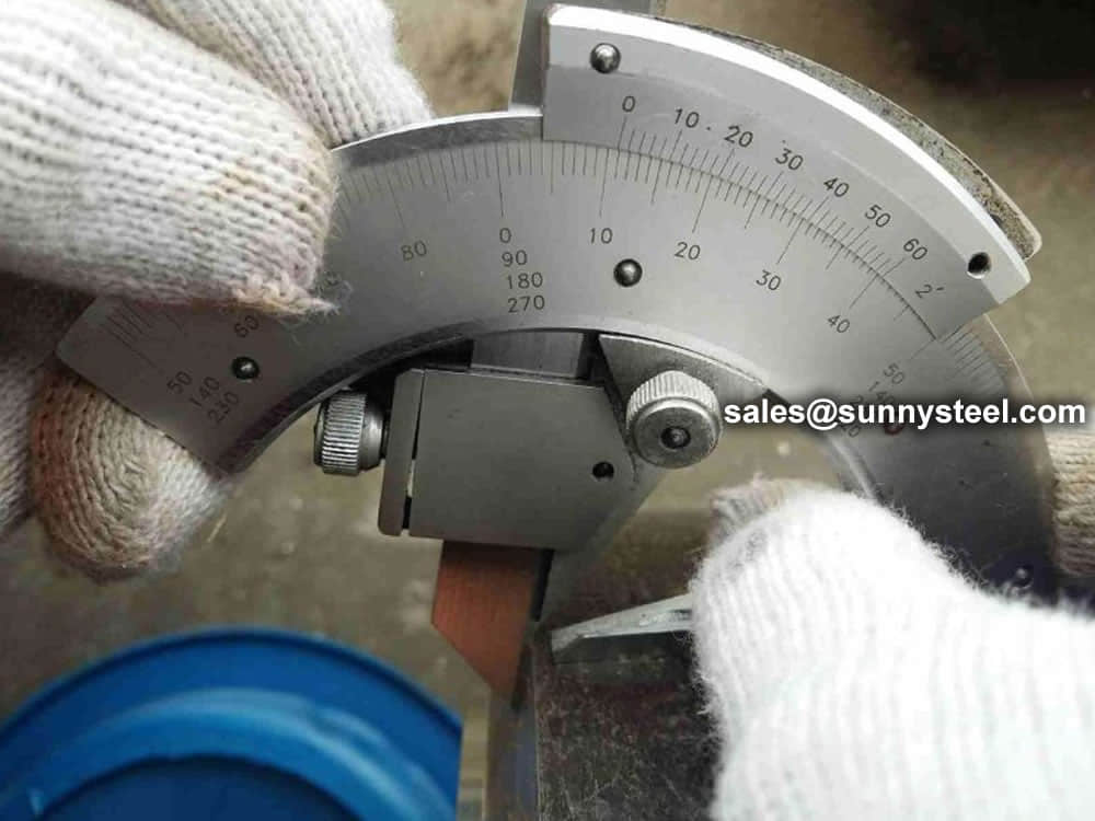
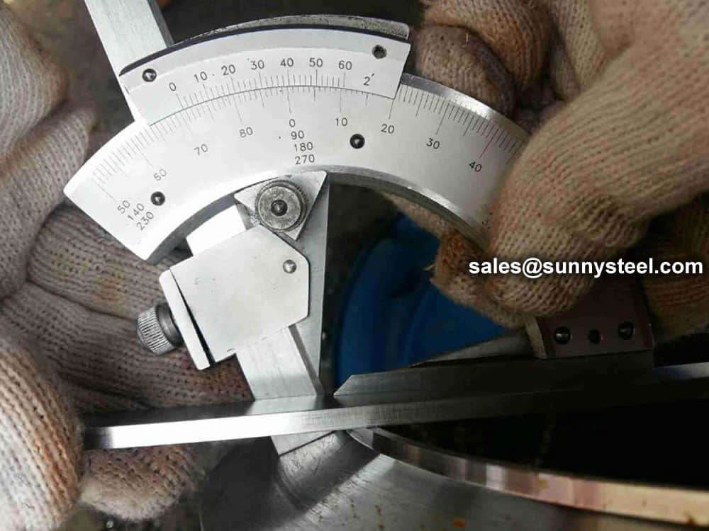
8.6 Preparation of ends
Tubes with wall thickness ≥ 3,2 mm shall be delivered with square cut ends. The ends shall be free from excessive burrs.
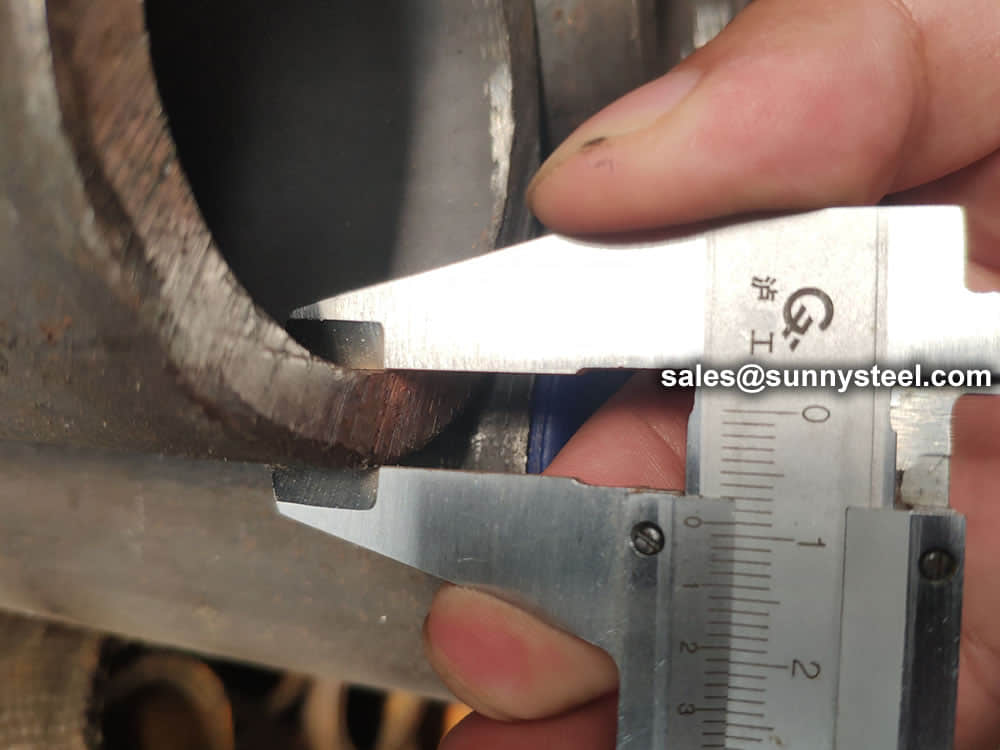
Option 7: The tubes with wall thickness ≥ 3.2 mm shall be delivered with bevelled ends (see Figure 1). The bevel shall have an angle α of 30°( +°5,-0°)with a root face C of 1,6 mm ± 0,8 mm, except that for wall thickness T greater than 20 mm, an agreed alternative bevel may be specified.
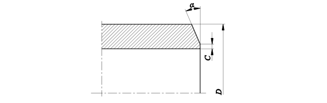
Key
D outside diameter
α bevel angle
C root face of bevelled end
Figure 1 — Tube end beve
8.7 Dimensions, masses and tolerances
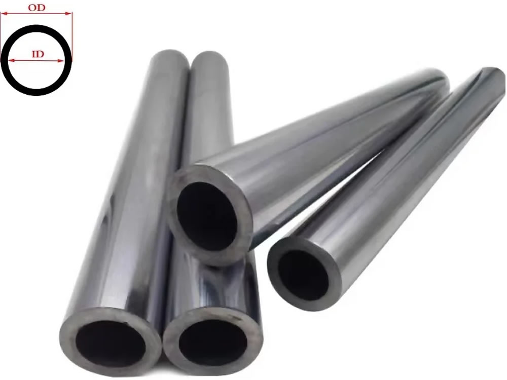
8.7.1 Diameter and wall thickness
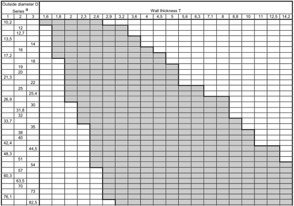
Tubes shall be delivered by outside diameter D and wall thickness T.
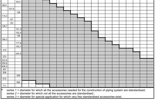
Preferred outside diameters D and wall thicknesses T have been selected from EN 10220 and are given in Table 7.
Dimensions which are different from those in Table 7 may be agreed.
8.7.2 Mass
For the mass per unit length the provisions of EN 10220 apply.
8.7.3 Lengths
Unless Option 8 is specified the tubes are delivered in random lengths. The delivery range shall be agreed at the time of enquiry and order.
Option 8: The tubes shall be delivered in exact lengths and the length shall be specified at the time of enquiry and order. For the tolerances, see 8.7.4.2.l
Table 7 — Preferred dimensions
Dimensions in millimetres
8.7.4 Tolerances
8.7.4.1 Tolerances on diameter and thickness
The diameter and the wall thickness of the tubes shall be within the tolerance limits given in Table 8.
Out-of-roundness is included in the tolerances on outside diameter and eccentricity is included in the tolerances on wall thickness.
Table 8 — Tolerances on outside diameter and on wall thickness
| Outside diameter D mm |
Tolerances on D | Tolerances on T for a T/D ratio | |||
|---|---|---|---|---|---|
| ≤ 0,025 | > 0,025 ≤ 0,050 |
> 0,050 ≤ 0,10 |
> 0,10 | ||
| D ≤ 219,1 | ± 1% or ± 0,5 mm whichever is the greater | ± 12,5 % or ± 0,4 mm whichever is the greater |
|||
| D > 219,1 | ± 20 % | ± 15 % | ± 12,5 % | ± 10 % a | |
a For outside diameters D ≥ 355,6 mm it is permitted to exceed the upper wall thickness locally by a further 5 % of the wall thickness T
8.7.4.2 Tolerances on exact lengths
The tolerances for exact lengths shall be as given in Table 9.
Table 9 — Tolerances on exact lengths
Dimensions in millimetres
| Length L | Tolerance on exact length |
|---|---|
| L ≤ 6 000 | + 10 0 |
| 6 000 < L ≤ 12 000 | +15 0 |
| L > 12 000 | +by agreement 0 |
9.1 Types of inspection
Conformity to the requirements of the order, for tubes in accordance with this Part of EN 10216, shall be verified by:
non-specific or specific inspection for quality TR1;
specific inspection for quality TR2.
When an inspection certificate 3.1 is specified, the material manufacturer shall state in the confirmation of the order whether he is operating according to a “quality-assurance system”, certified by a competent Body established within the Community, and having undergone a specific assessment for materials.
NOTE See the EU Directive 97/23/EC, Annex I, section 4.3 third paragraph and for further information the Guidelines of the EU Commission and the Member States for its interpretation (see e.g. Guidelines 7/2 and 7/16).
9.2 Inspection documents
9.2.1 Types of inspection documents
The following inspection documents, in accordance with EN 10204, shall be issued;
- test report 2.2 for quality TR1;
- inspection certificate 3.1 for quality TR2.
Option 9: One of the following inspection documents, specified by the purchaser, shall be issued:
- for quality TR1 specific inspection with inspection certificate 3.2;
- for quality TR2, an inspection certificate 3.2.
If an inspection certificate 3.2 is specified, the purchaser shall notify the manufacturer of the name and address of the organization or person who is to carry out the inspection and produce the inspection document, and it shall be agreed which party shall issue the certificate.
Document 3.1 and 3.2 are to be validated by the manufacturer’s authorized representative.
9.2.2 Content of inspection documents
9.2.2.1 The content of the inspection document shall be in accordance with EN 10168 as shown in 9.2.2.2 and9.2.2.3.
In all types of inspection documents, a statement on the conformity of the products delivered with the requirements of this specification and the order shall be included.
9.2.2.2 For tubes supplied with non-specific inspection, the test report shall contain the following codes and information:
A commercial transactions and parties involved;
B description of products to which the inspection document applies;
C02 direction of test pieces;
C10–C13 tensile test;
C71–C92 chemical composition;
D01 marking and identification, surface appearance, shape and dimensional properties;
D02–D99 leak-tightness test;
Z validation.
9.2.2.3 For tubes supplied with specific inspection the inspection certificate shall contain the following codes and information:
A commercial transactions and parties involved;
B description of products to which the inspection document applies
C02–C03 direction of test pieces and testing temperature;
C10–C13 tensile test;
C40–C43 impact test, if applicable;
C71–C92 chemical composition on cast analysis (product analysis if applicable);
D01 marking and identification, surface appearance, shape and dimensional properties;
D02–D99 leak-tightness test; NDT if applicable;
Z validation.
In addition, for inspection document 3.1 the manufacturer shall state the references to the certificate (see 9.1) of the appropriate “quality-assurance system“, if applicable
9.3 Summary of inspection and verification testing
Table 10 — Summary of inspection and verification testing for quality TR1
| Type of inspection and test | Frequency of testing | Refer to | ||
|---|---|---|---|---|
| Non-specific inspection |
Specific inspection |
|||
| Mandatory tests |
Cast analysis | One representative result per delivery item |
One per cast | 8.2.1 and 11.1 |
| Tensile test | One per test unit | 8.3.2 and 11.2 | ||
| Leak-tightness test | Each tube | 11.4 | ||
| Dimensional inspection | See 11.5 | |||
| Visual examination | See 11.6 | |||
| Optional test |
Wall thickness measurement away from tube ends (Option 12) |
See 11.5 |
Table 11 — Summary of inspection and verification testing for quality TR2
| Type of inspection and test | Frequency of testing | Refer to | |
|---|---|---|---|
| Mandatory tests | Cast analysis | One per cast | 8.2.1 and 11.1 |
| Tensile test | One per test unit | 8.3.1 and 11.2 | |
| Impact test at 0 °C | 8.3.1 and 11.3 | ||
| Leak-tightness test | Each tube | 11.4 | |
| Dimensional inspection | See 11.5 | ||
| Visual examination | See 11.6 | ||
| Optional tests | Product analysis (Option 3) | One per cast | 8.2.2 and 11.1 |
| Longitudinal impact test at -10 °C (Option 4) | One per test unit | 8.3.1 and 11.3 | |
| Wall thickness measurement away from tube ends (Option 12) | See 11.5 | ||
| NDT for detection of longitudinal imperfections (Option 6) | Each tube | 11.7 | |
10.1 Frequency of tests
10.1.1 Test unit
In case of specific inspection, a test unit shall comprise:
Quality TR1: Tubes of the same specified outside diameter and wall thickness, the same steel grade, the same manufacturing process and, if applicable, the same normalising treatment in a continuous furnace or heat-treated in the same furnace charge in a batch-type furnace.
Quality TR2: Tubes of the same specified outside diameter and wall thickness, the same steel grade, the same cast, the same manufacturing process and, if applicable, the same normalising treatment in a continuous furnace or heat-treated in the same furnace charge in a batch-type furnace. Tubes with specified outside diameter less than or equal to 76.1 mm need not be separated by cast unless Option 10 is specified.
The number of tubes, in manufacturing lengths, per test unit shall conform to Table 12.
The manufacturing length (e.g. the rolled length after the normalising forming process) may differ from the delivery length providing there is no additional HT after cutting the manufacturing lengths into individual lengths.
Option 10: Tubes with specified outside diameter less than or equal to 76,1 mm shall be separated by cast for quality TR2 .
Table 12 — Number of tubes per test unit
| Outside diameter D(mm) | Maximum number of tubes per test unit | |
|---|---|---|
| Quality TR1 | Quality TR2 | |
| D ≤ 114,3 | 400 | 200 |
| 114,3 < D ≤ 323,9 | 200 | 100 |
| D > 323,9 | 100 | 50 |
10.1.2 Number of sample tubes per test unit
One sample tube shall be taken from each test unit.
10.2 Preparation of samples and test pieces
10.2.1 Selection and preparation of samples for product analysis Samples for product analysis shall be taken from the test pieces or samples for mechanical testing or from the whole thickness of the tube at the same location as the mechanical test samples, in accordance with EN ISO 14284.
10.2.2 Location, orientation and preparation of samples and test pieces for mechanical tests
10.2.2.1 General
Samples and test pieces shall be taken at the tube ends and in accordance with the requirements of EN ISO 377.
10.2.2.2 Test pieces for tensile test
The test pieces for tensile test shall be prepared in accordance with EN ISO 6892-1.
At the manufacturer's discretion:
for tubes with an outside diameter D ≤ 219,1 mm the test piece shall be either a full tube section or a strip section and shall be taken in a direction longitudinal to the axis of the tube;
for tubes with an outside diameter D > 219,1 mm the test piece shall either a machined test piece with circular cross section from an unflattened sample or a strip section and be taken in a direction either longitudinal or transverse to the axis of the tube.
10.2.2.3 Test pieces for impact test
Three standard Charpy V-notch test pieces shall be prepared in accordance with EN ISO 148-1. If the wall thickness is such that standard test pieces cannot be produced without flattening of the section, then test pieces of width less than 10 mm, but not less than 5 mm shall be prepared; the largest obtainable width shall be used.
Where test pieces at least 5 mm width cannot be obtained, the tubes shall not be subjected to impact testing.
Unless otherwise specified (see Option 4), the test pieces shall be taken transverse to the tube axis unless D min , as calculated by the following equation, is greater than the specified outside diameter, in which case longitudinal test pieces shall be used:
D min = (T-5) + [ 756,25 / (T-5) ] (1)
The test pieces shall be prepared such that the axis of the notch is perpendicular to the surface of the tube,see Figure 2.
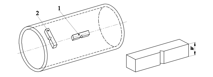
Key
1 longitudinal test piece
2 transverse test piece
w specimen width
Figure 2 — Impact test piece orientation
11.1 Chemical analysis
The elements to be determined and reported shall be those specified in Table 2. The choice of a suitable physical or chemical analytical method for the analysis shall be at the discretion of the manufacturer. In cases of dispute, the method used shall be agreed between manufacturer and purchaser taking into account CEN/TR 10261.
11.2 Tensile test
The test shall be carried out at room temperature in accordance with EN ISO 6892-1, and the following shall be determined:
the tensile strength (R m );
the upper yield strength (R eH ) or if a yield phenomenon is not present the 0,2 % proof strength (R p0,2 );
the percentage elongation after fracture with a reference to a gauge length ( L 0 ) of So ⋅ 65 , 5 ; if a nonproportional test piece is used, the percentage elongation value shall be converted to the value for a gauge length So Lo ⋅ = 65 , 5 using the conversion tables in EN ISO 2566-1.
11.3 Impact test
11.3.1 The test shall be carried out (but see 10.2.2.3) in accordance with EN ISO 148-1 at 0 °C and, if option 4 is specified, at -10 °C.
11.3.2 The mean value of the three test pieces shall meet the requirements given in Table 5 and Table 6. One individual value may be below the specified value, provided that it is not less than 70 % of that value.
11.3.3 If the width (W) of the test piece is less than 10 mm, the measured impact energy (KV p ) shall be converted to the calculated impact energy( KV c ) using the following equation:

where
KV c is the calculated impact energy, in joules;
KV p is the measured impact energy, in joules;
W is the width of the test piece, in millimetres.
The calculated impact energy KV c shall conform to the requirements given in 11.3.2.
11.3.4 If the requirements of 11.3.2 are not met, then an additional set of three test pieces may be taken at the discretion of the manufacturer from the same sample and tested. To consider the test unit as conforming, after testing the second set, the following conditions shall be satisfied simultaneously:
the average value of the six tests shall be equal to or greater than the specified minimum value;
not more than two of the six individual values may be lower than the specified minimum value;
not more than one of the six individual values may be lower than 70 % of the specified minimum average value.
11.3.5 The dimensions in millimetres of the test pieces, the measured impact energy values and the resulting average value shall be reported.
11.4 Leak tightness test
11.4.1 Hydrostatic test
The hydrostatic test shall be carried out at a test pressure of 70 bar 1) or at a test pressure P calculated using the following equation, whichever is lower:

where
P is the test pressure, in bar;
D is the specified outside diameter, in millimetres;
T is the specified wall thickness, in millimetres;
S is the stress, in MPa, corresponding to 70 % of the specified minimum yield strength (see Table 5 and Table 6) for the steel grade concerned.
The test pressure shall be held for not less than 5 s for tubes with an outside diameter D less than or equal to 457 mm and for not less than 10 s for tubes with an outside diameter D greater than 457 mm.
The tube shall withstand the test without showing leakage.
NOTE This hydrostatic leak-tightness test is not a strength test.
11.4.2 Electromagnetic test
The test shall be carried out in accordance with EN ISO 10893-1.
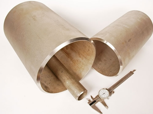
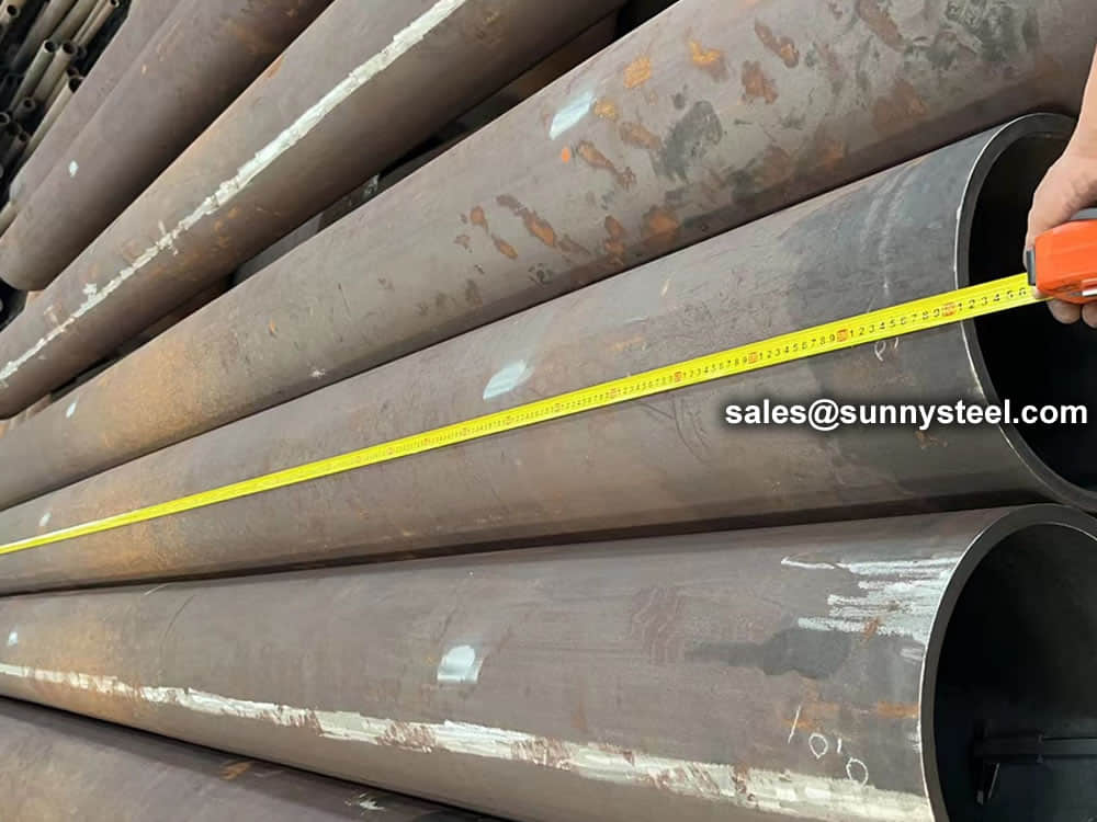
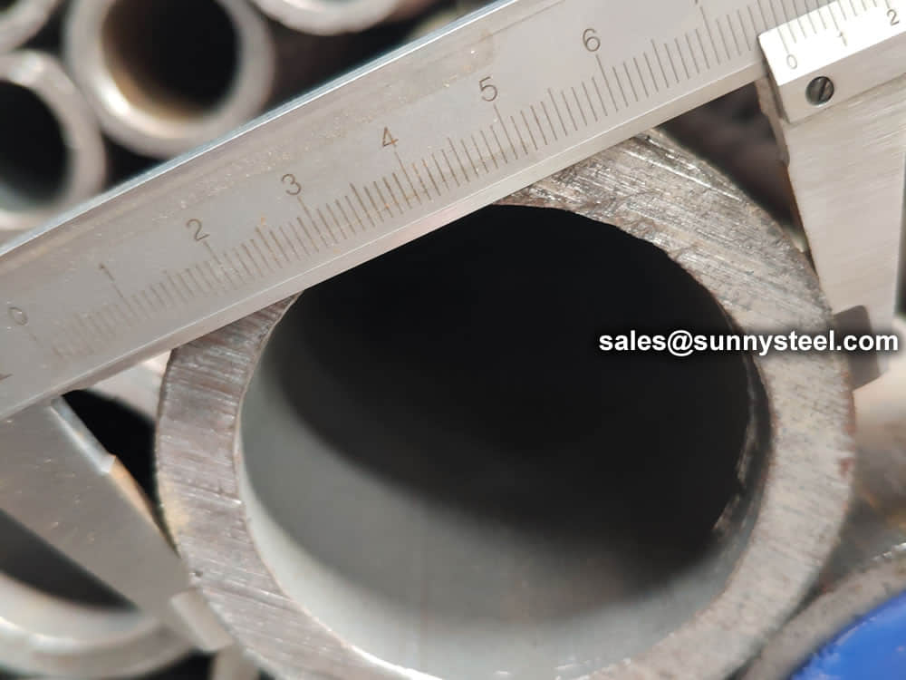
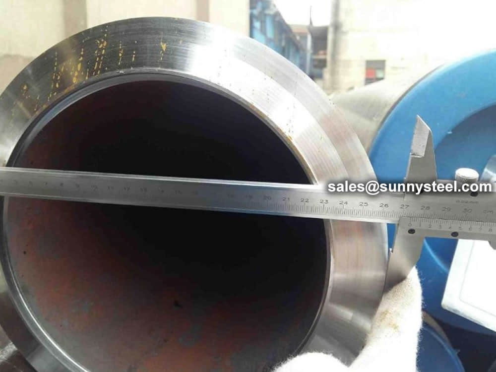
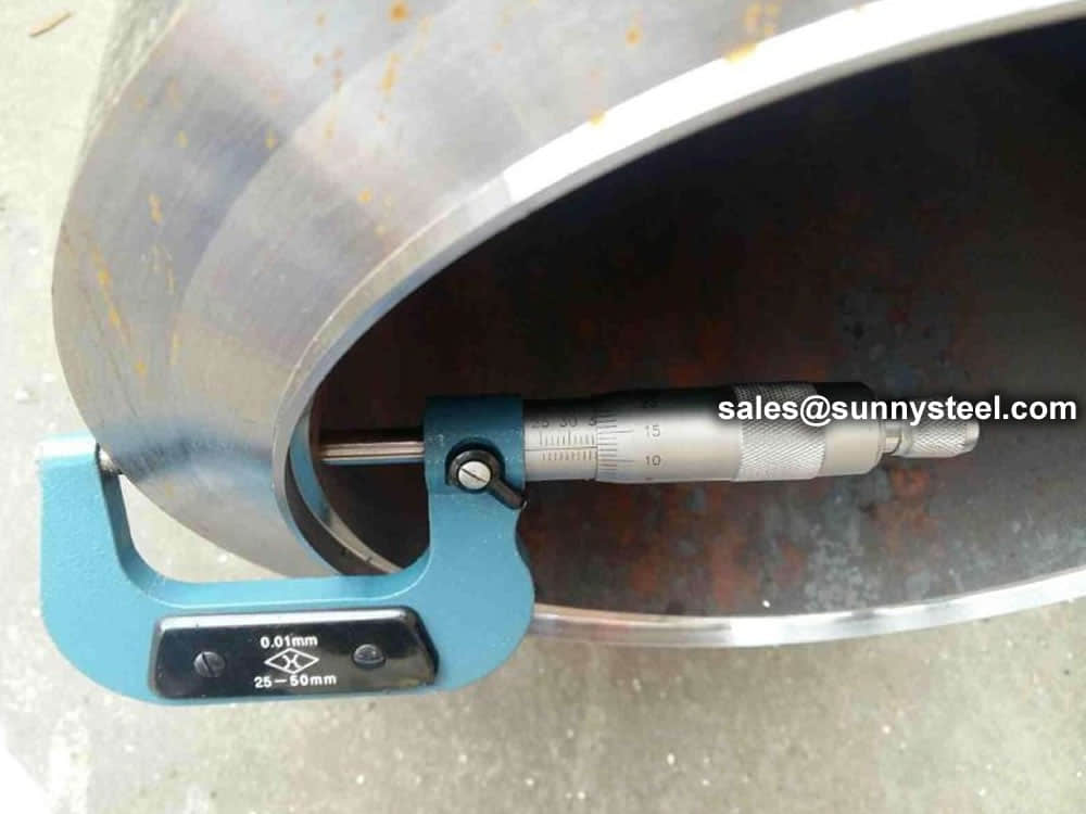
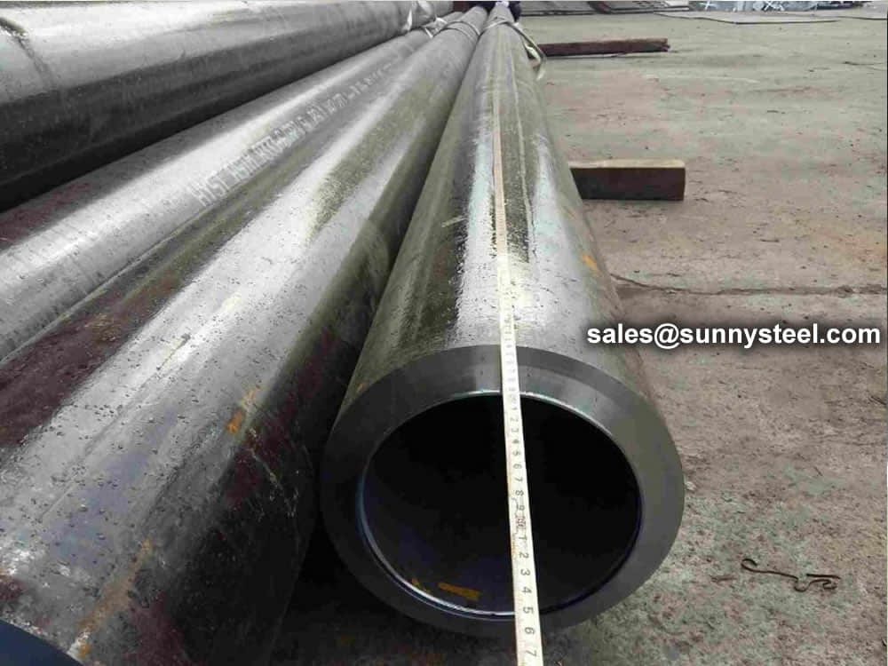
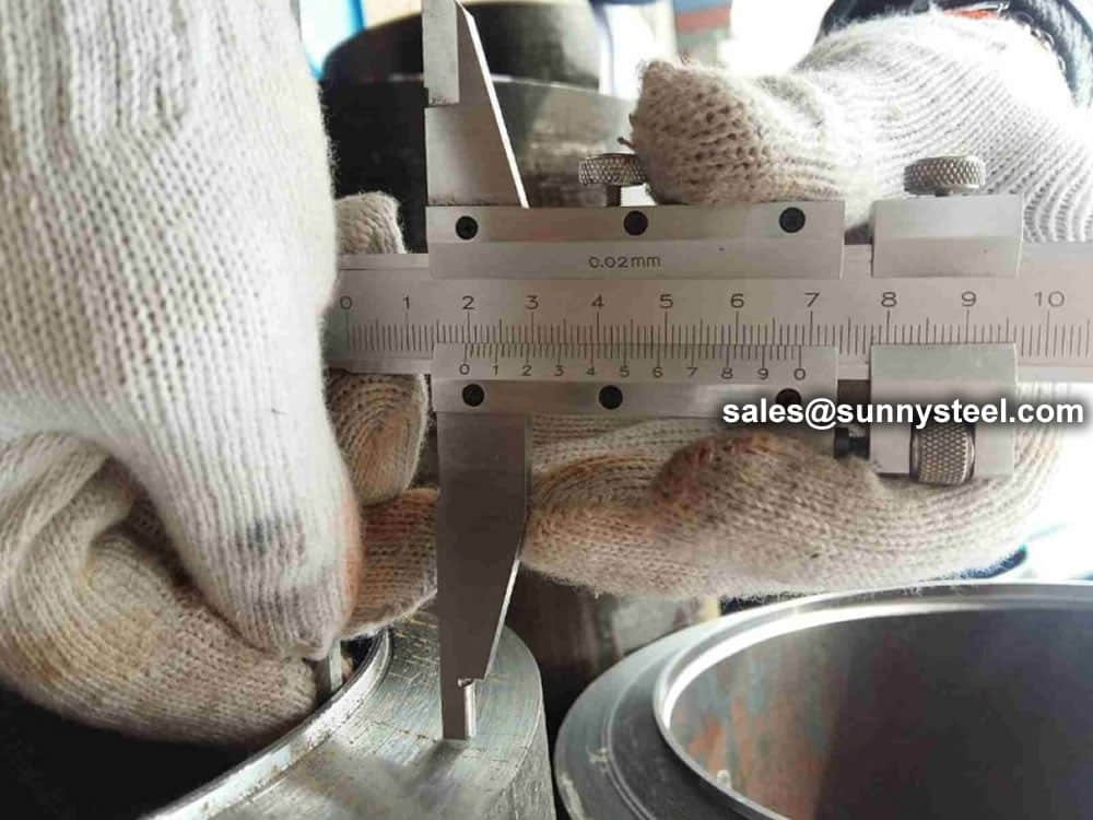
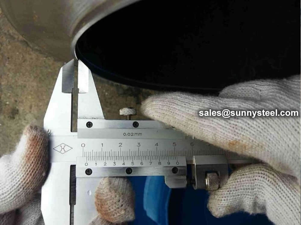
11.5 Dimensional inspection
Specified dimensions, including straightness, shall be verified.
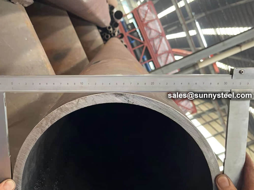
The outside diameter shall be measured at tube ends. For tubes with outside diameter D ≥ 406,4 mm, the diameter may be measured using a circumference tape.
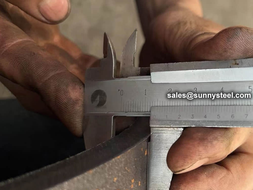
Unless Option 11 is specified the wall thickness shall be measured at both tube ends.
Option 11: The wall thickness shall be measured away from the tube ends in accordance with an agreed procedure.
11.6 Visual examination
Tubes shall be visually examined to ensure conformity to the requirements of 8.4.1.
11.7 Non-Destructive Testing
When Option 6 is specified, the tubes of quality TR2 shall be subjected to Non-Destructive testing for the detection of longitudinal imperfections in accordance with EN ISO 10893-2, EN ISO 10893-3 or EN ISO 10893-10 to acceptance level 3, sub-category C, where applicable.
Regions at the tube ends not automatically tested shall either be subjected to manual/semi-automatic ultrasonic testing in accordance with EN ISO 10893-10 or be cropped off.
11.8 Retest, sorting and reprocessing
For retest, sorting and reprocessing the requirements of EN 10021 shall apply.
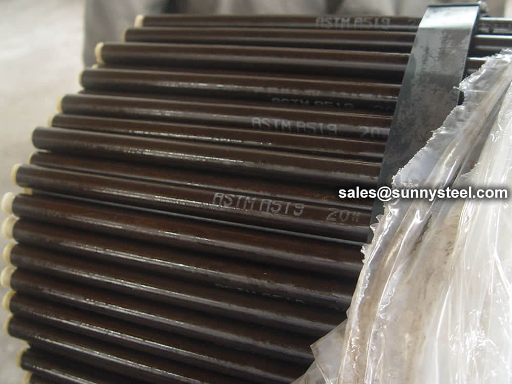
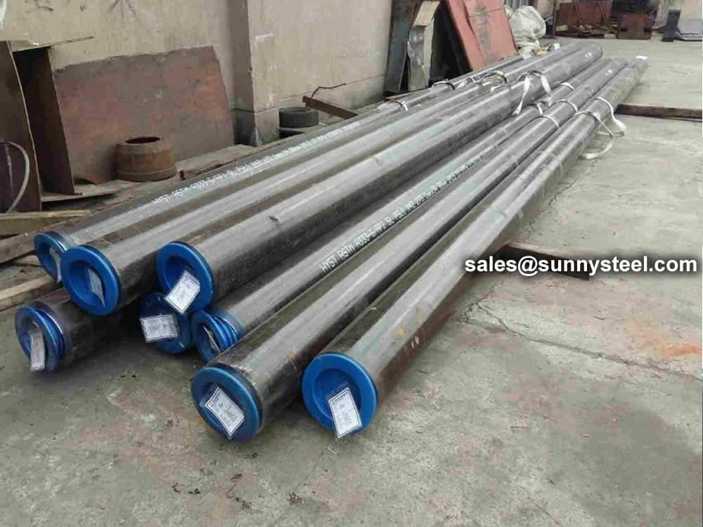
12.1 Marking to be applied
The marking shall be indelibly marked on each tube at least at one end. For tubes with outside diameter D ≤ 51 mm the marking on tubes may be replaced by the marking on a label attached to the bundle or box.
The marking shall include the following information:
the manufacturer's name or trade mark;
the number of this European Standard and the steel name (see 5.2).
In addition in case of specific inspection:
the cast number or a code number;
the mark of the inspection representative;
an identification number (e.g. order or item number), which permit the correlation of the product or delivery unit to related documents.
Example of marking:
EXAMPLE X – EN 10216-1 - P265TR2 - Y - Z 1 - Z 2
where
X is the manufacturer's mark;
Y is the cast number or the code number;
Z 1 is the mark of the inspection representative;
Z 2 is the identification number.
12.2 Additional marking
Option 12: Additional marking, as agreed upon at the time of the enquiry and order, shall be applied.
The tubes shall be delivered without a temporary protective coating.
Option 13: A temporary protective coating or durable coating and/or lining shall be applied.
DIN steel heat exchanger tubes, meeting German Industrial Standards, are constructed from high-temperature and corrosion-resistant steel, specifically designed for efficient heat exchange applications.
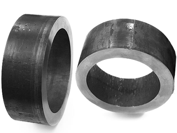
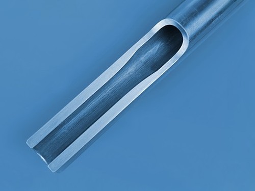
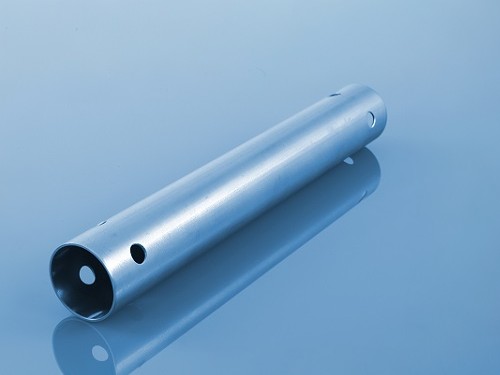
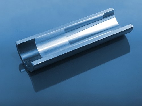
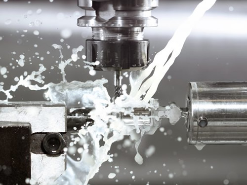
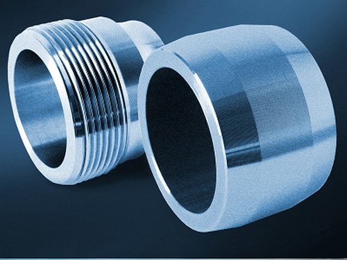
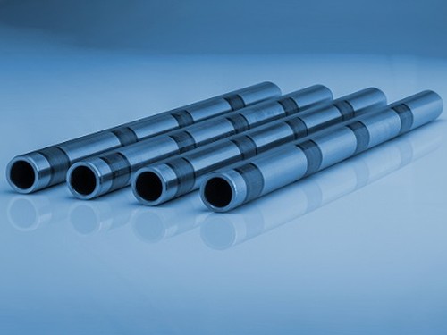
With years of expertise, we provide a diverse array of steel tube processing options. From sawing and machining tube blanks to intricate bending and upsetting operations, we actively assist you throughout your projects.
Our capabilities extend to eccentricity reduction and concentricity enhancement through turning and grinding. We excel in creating complex geometries using processes like rotary swaging and axial forming. Additionally, we offer property modifications via partial heat treatment, ensuring tailored solutions for your specific needs.


Alloy steel pipes are ideally suitable for chemical, petrochemicals, and other energy-related applications.
The alloy steel pipe adopts high quality carbon steel, alloy structural steel and stainless & heat resisting steel as raw material through hot rolling or cold drawn to be made.
Alloy steel can be used in process area where carbon steel has limitation such as
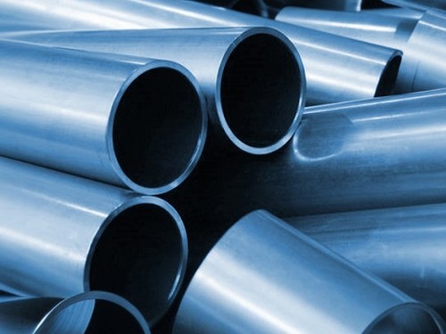
As an important element of steel products, alloy steel pipe can be divided into seamless steel pipe and welded steel pipe according to the manufacturing technique and tube billet shape.
Here you can see the common alloy steel grade that you will come across.
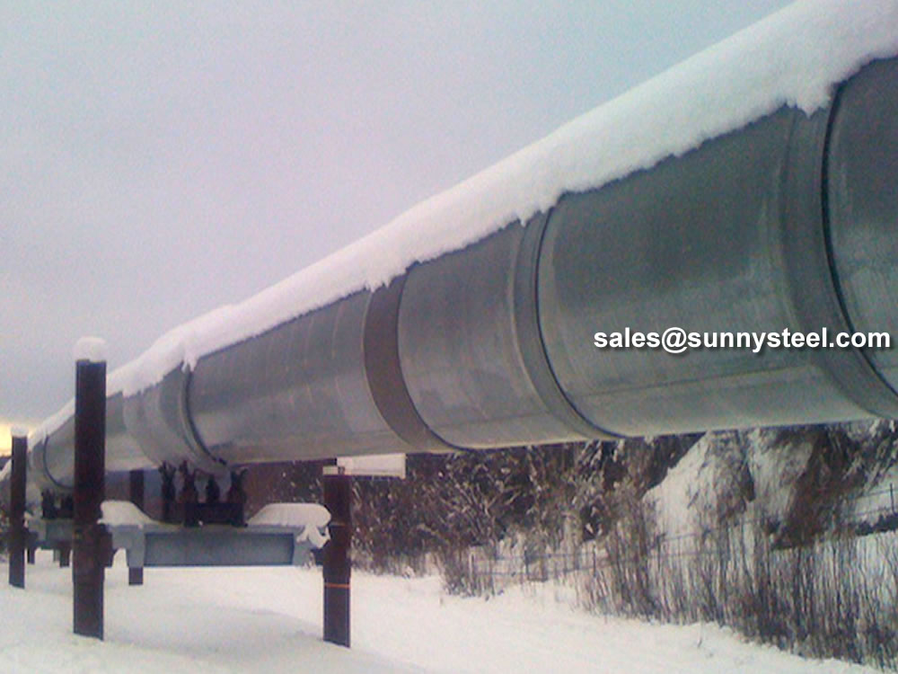
There are many kinds of materials used for transport in industrial production. Specifically we will have more choices and it is not limited to the use of alloy steel pipe. But even in the face of more choices, many people tend to choose alloy steel pipe. People make their own choices will have their own reasons. This means the alloy steel pipe application has its own advantages. Compared with transmission lines made of other materials, after it meets the basic application requirements, its quantity is lighter. Then in the practical application of alloy steel pipe, it will have more advantages because of this. Besides its physical characteristic advantage, it also has economic advantages. The wide application of alloy steel pipe is with kinds of reasons. So in practical usage, we can exploit the advantages to the full, in this way can we get more profits in these applications of alloy steel pipe.
The transportation of kinds of gases or liquids in production needs to rely on alloy steel pipe. This shows that the actual role of alloy steel pipe application is important. High temperature resistant and low temperature resistant is the tolerance of temperature. In the practical application of alloy steel pipe, there will be many materials need to be transported. However their temperatures are not the same. So this can be the basic requirement to alloy steel pipe. It needs more corrosion resistance. Corrosion resistant material is the best material during transporting, because it is corrosion resistant. So it can be used in more occasions. And it is definitely very convenient for users.
Can be 100% recycled, environmentally friendly, energy-saving, resource conservation, national strategy, national policy to encourage the expansion of the field of application of high-pressure alloy pipe. Of alloy steel pipe total consumption accounted steel in the proportion is only half of the developed countries, to expand the field of use of the alloy steel pipe to provide a wider space for the development of the industry. The future needs of the average annual growth of China’s high-pressure alloy steel pipe long products up to 10-12%.
Alloy Steel pipe contains substantial quantities of elements other than carbon such as nickel, chromium, silicon, manganese, tungsten, molybdenum, vanadium and limited amounts of other commonly accepted elements such as manganese, sulfur, silicon, and phosphorous.
Our team of experienced sales specialists proudly partners with gas and chemical processors, power generation plants, oil refineries, and related industries to offer piping components and value-added services.
The biggest advantages of alloy steel pipe can be 100% recycled, environmentally friendly, energy-saving, resource conservation, national strategy, national policy to encourage the expansion of the field of application of high-pressure alloy pipe. Of alloy tube total consumption accounted steel in the proportion is only half of the developed countries, to expand the field of use of the alloy tube to provide a wider space for the development of the industry. According to the Chinese Special Steel Association alloy pipe Branch Expert Group, the future needs of the average annual growth of China’s high-pressure alloy pipe long products up to 10-12%.
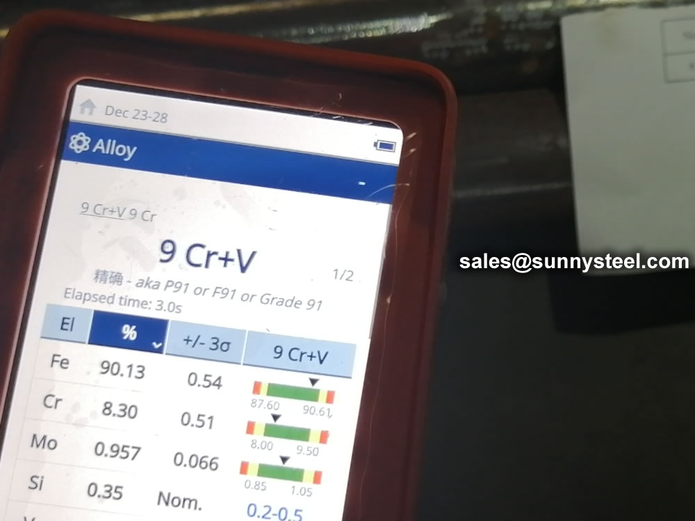
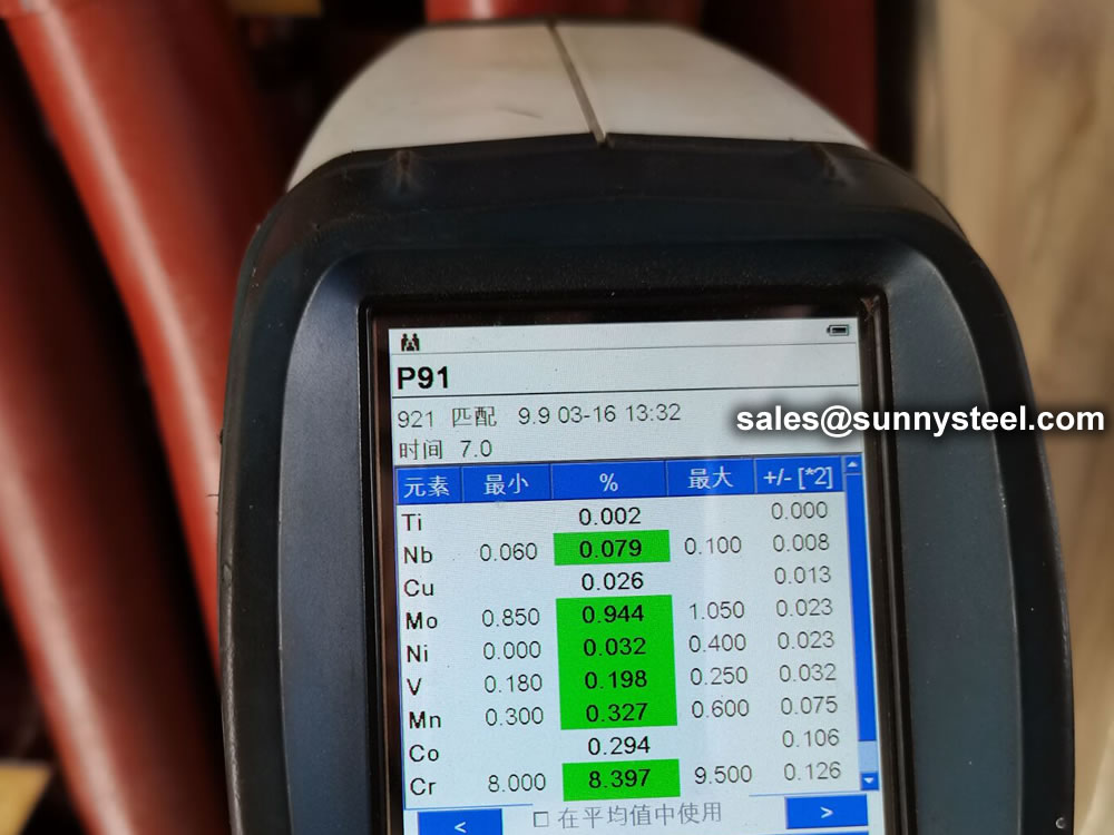
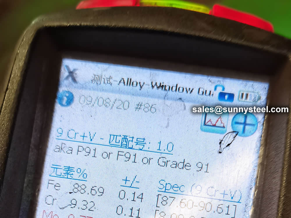
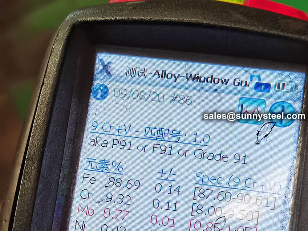
Chemical composition inspection, mechanical properties test(tensile strength,yield strength, elongation, flaring, flattening, bending, hardness, impact test), surface and dimension test,no-destructive test, hydrostatic test.
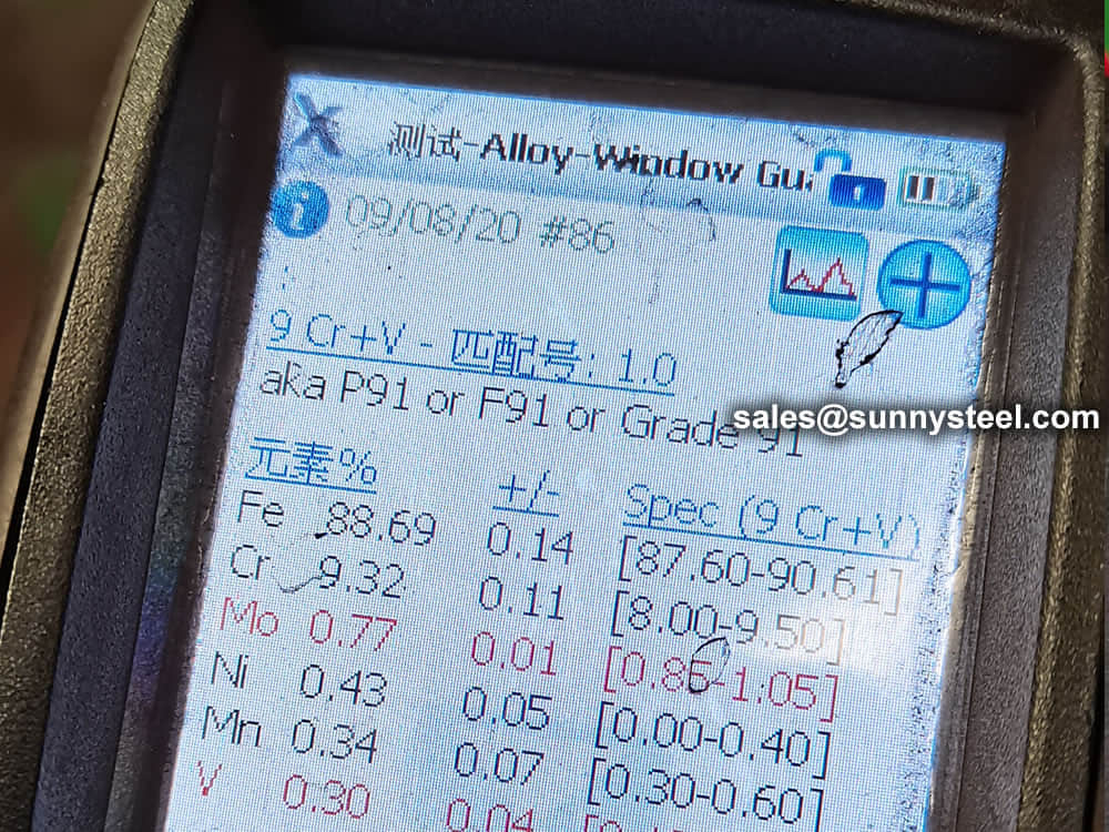
identification of the chemical composition of the metal used to manufacture the fitting. Uses PMI sensors, including X-ray fluorescence or optical emission spectrometry.
Steel pipe delivery status(condition): cold / hard (BK), cold / soft (BKW), after cold stress relief annealing (BKS), annealing (GBK), normalized (NBK).
| Term | Symbol | Explanation |
|---|---|---|
| Cold-finished/hard (cold-finished as-drawn) | BK | No heat treatment after the last cold-forming process. The tubes therefore have only low deformability. |
| Cold-finished/soft (lightly cold-worked) | BKW | After the last heat treatment there is a light finishing pass (cold drawing) With proper subsequent processing, the tube can be cold-formed (e.g. bent, expanded) within certain limits. |
| Annealed | GBK | After the final cold-forming process the tubes are annealed in a controlled atmosphere or under vacuum. |
| Normalized | NBK | The tubes are annealed above the upper transformation point in a controlled atmosphere or under vacuum. |
The general cold strip mills, volume should go through continuous annealing (CAPL unit) to eliminate cold hardening and rolling stress, or batch annealing reach the mechanical properties of the corresponding standard specifies. Cold rolled steel surface quality, appearance, dimensional accuracy better than hot-rolled plate, and right-rolled thin product thickness is about 0.18mm, so the majority of users favor.
Cold rolled steel coil substrate products deep processing of high value-added products. Such as electro-galvanized, hot dip galvanized, electro-galvanized fingerprint resistant, painted steel roll damping composite steel, PVC laminating steel plates, etc., so that the excellent quality of these products has a beautiful, high resistance to corrosion, has been widely used.
Cold rolled steel coil finishing after annealing, cut the head, tail, trimming, flattening, smooth, heavy volume, or longitudinal clipboard. Cold-rolled products are widely used in automobile manufacturing, household electrical appliances, instruments, switches, buildings, office furniture and other industries. Steel plate strapping package weight of 3 to 5 tons. Flat sub-volume typically 3 to 10 tons / volume. Coil diameter 6m.
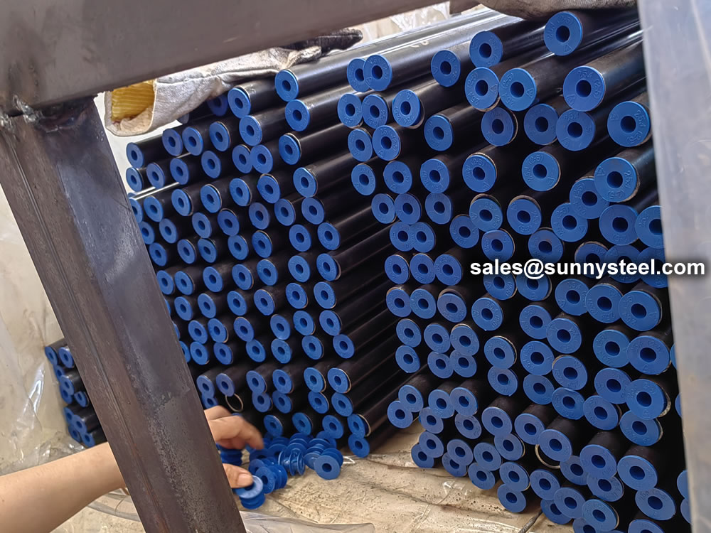
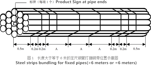
Bare packing/bundle packing/crate packing/wooden protection at the both sides of tubes and suitably protected for sea-worthly delivery or as requested.
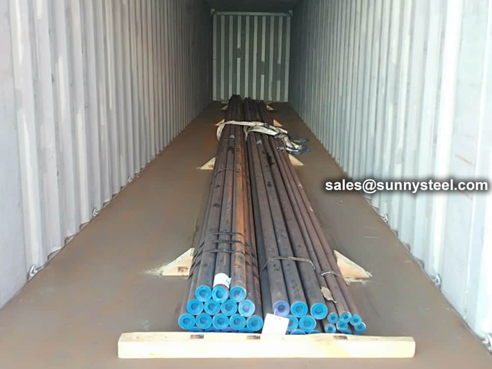
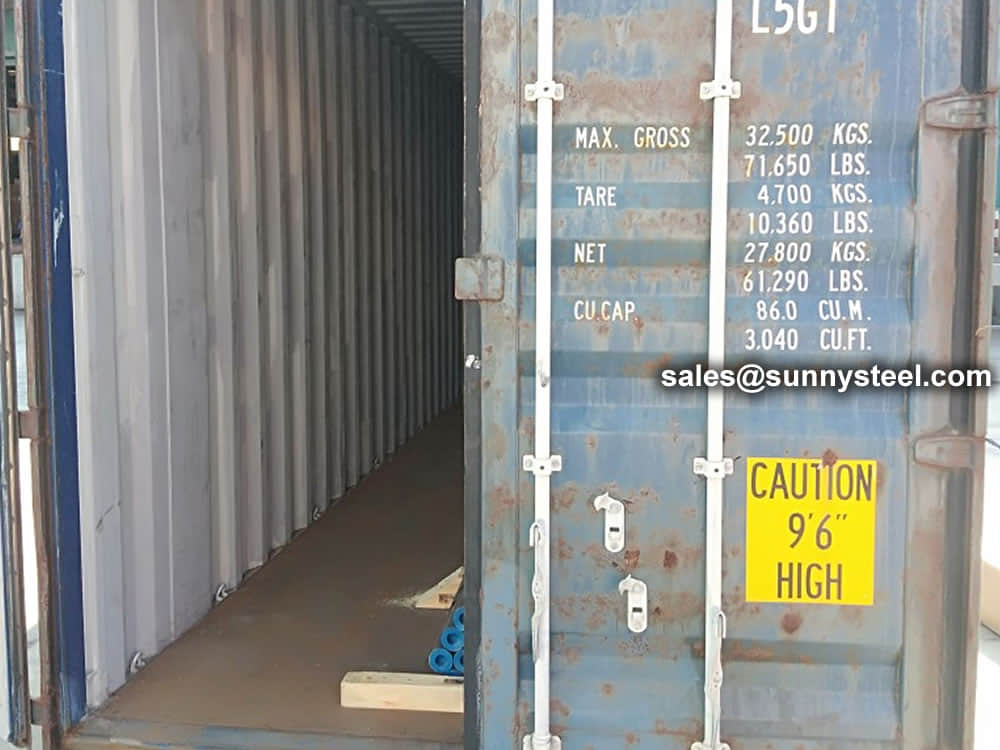
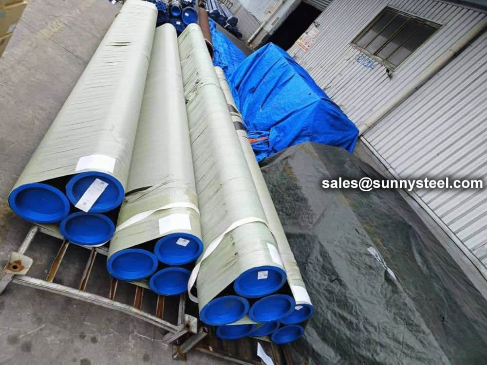
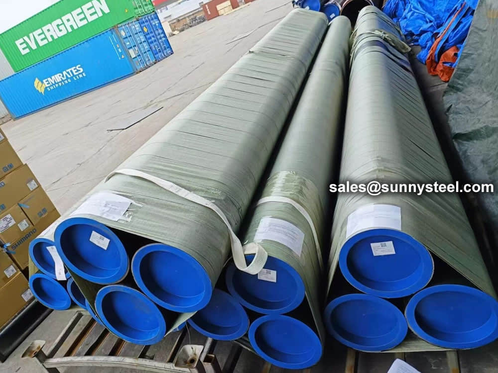
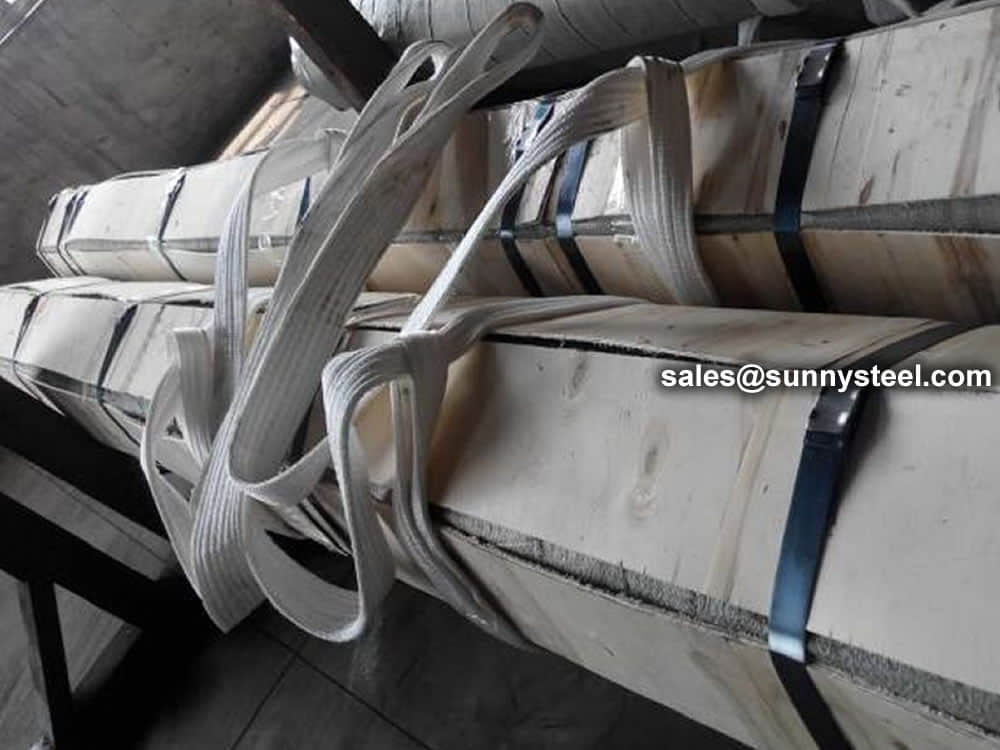
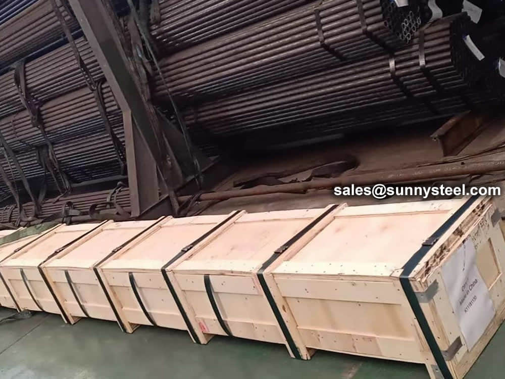
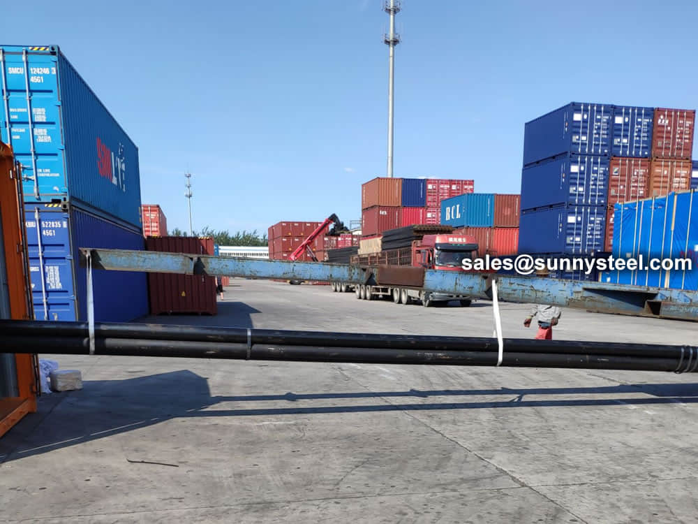
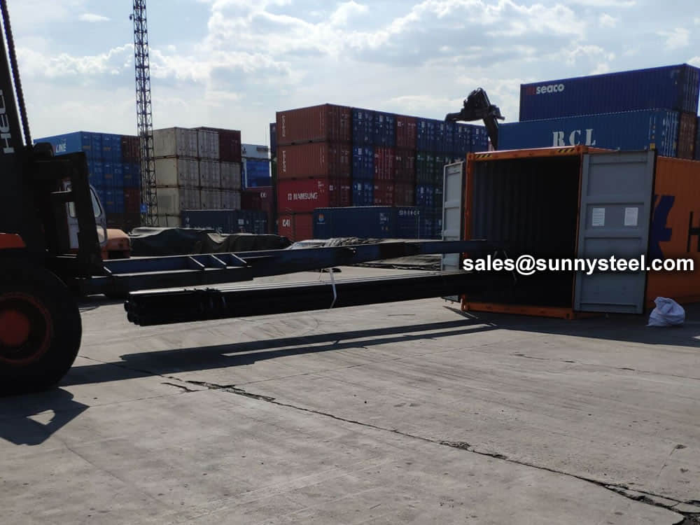
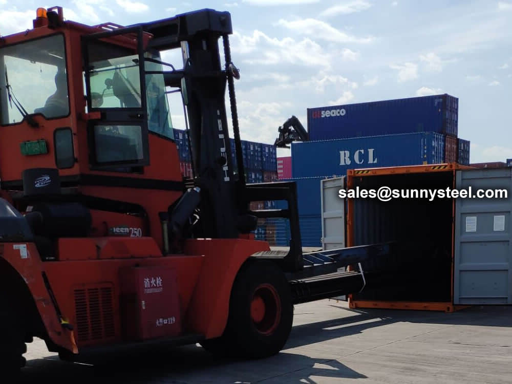

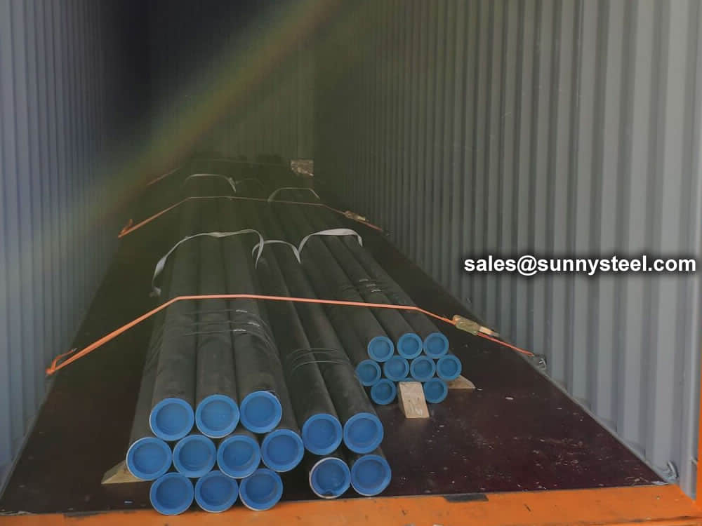
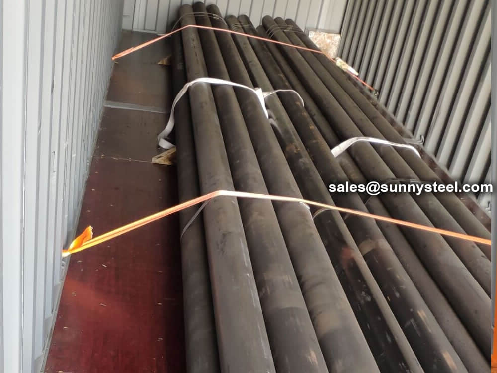
There are probably hundreds of different methods for packing a pipe, and most of them have merit, but there are two principles that are vital for any method to work prevent rusting and Sea transportation security.
Our packing can meet any needs of the customers.


Our team of experienced sales specialists proudly partners with gas and chemical processors, power generation plants, oil refineries, and related industries to offer piping components and value-added services.
Alloy steels are made by combining carbon steel with one or several alloying elements, such as manganese, silicon, nickel, titanium, copper, chromium and aluminum. These metals are added to produce specific properties that are not found in regular carbon steel. The elements are added in varying proportions (or combinations) making the material take on different aspects such as increased hardness, increased corrosion resistance, increased strength, improved formability (ductility); the weldability can also change.
Commonly used alloying elements and their effects are listed in the table given below.
| Alloying Elements | Effect on the Properties |
|---|---|
| Chromium | Increases Resistance to corrosion and oxidation. Increases hardenability and wear resistance. Increases high temperature strength. |
| Nickel | Increases hardenability. Improves toughness. Increases impact strength at low temperatures. |
| Molybdenum | Increases hardenability, high temperature hardness, and wear resistance. Enhances the effects of other alloying elements. Eliminate temper brittleness in steels. Increases high temperature strength. |
| Manganese | Increases hardenability. Combines with sulfur to reduce its adverse effects. |
| Vanadium | Increases hardenability, high temperature hardness, and wear resistance. Improves fatigue resistance. |
| Titanium | Strongest carbide former. Added to stainless steel to prevent precipitation of chromium carbide. |
| Silicon | Removes oxygen in steel making. Improves toughness. Increases hardness ability |
| Boron | Increases hardenability. Produces fine grain size. |
| Aluminum | Forms nitride in nitriding steels. Produces fine grain size in casting. Removes oxygen in steel melting. |
| Cobalt | Increases heat and wear resistance. |
| Tungsten | Increases hardness at elevated temperatures. Refines grain size. |
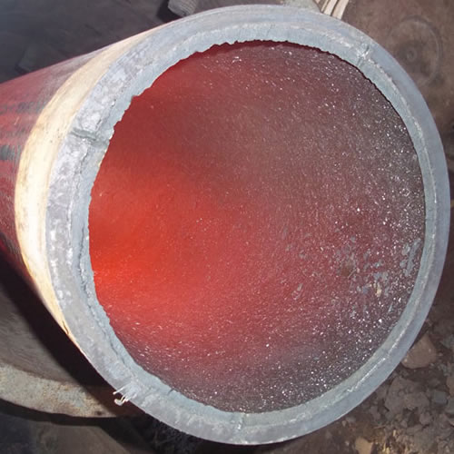
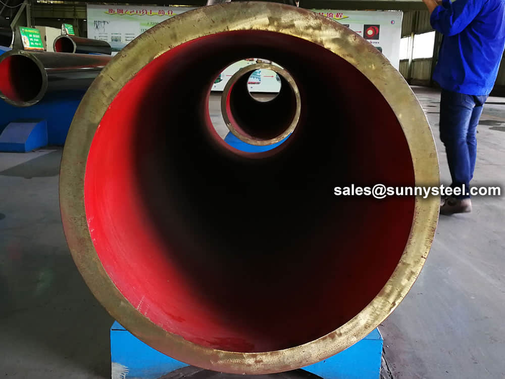
Ceramic lined pipe is made through self-propagating high-temperature synthesis (SHS) technique.
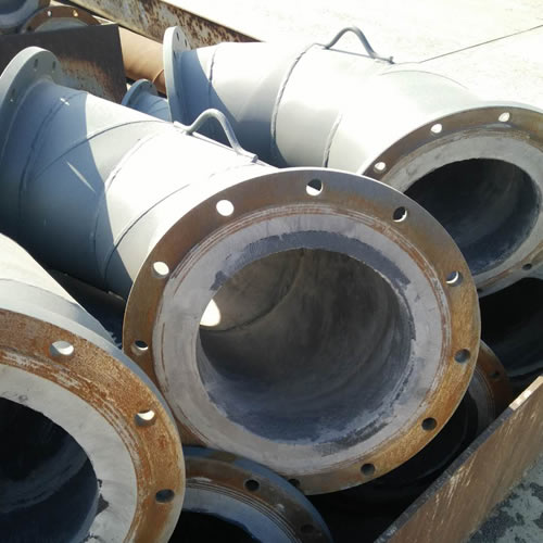
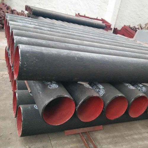
Cast basalt lined steel pipe is composed by lined with cast basalt pipe, outside steel pipe and cement mortar filling between the two layers.
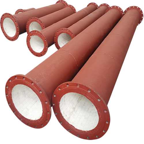
Ceramic tile lined pipes have very uniform coating of specially formulated ceramic material that is affixed to the inner of the pipe.
The material of the rare earth alloy wear-resistant pipe is ZG40CrMnMoNiSiRe, which is also the grade of rare earth alloy steel.
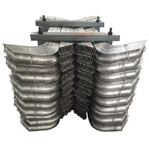
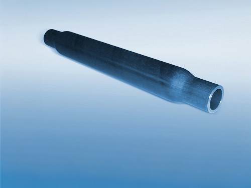
Tubes Erosion Shields are used to protect boiler tubing from the highly erosive effects of high temperatures and pressures thereby greatly extending tube life.
The ASTM A213 T91 seamless tubes are primarily used for boiler, superheater, and heat-exchanger.

When you partner with Sunny Steel, you can stop worrying about meeting deadlines thanks to our responsive and timely service. You'll also say goodbye to unnecessary shopping around. Instead, you'll get white glove service from an expert who understands your needs and can get you the materials you need quickly.